Introduction
In the US, Canada, and Latin America fire, smoke, and combination fire and smoke dampers are used in two general categories:
In the US, Canada, and Latin America fire, smoke, and combination fire and smoke dampers are used in two general categories:
- Containment of fire and/or smoke to maintain building compartmentation. These are installed based on Chapter 7 of the International Building Code (IBC) which is the primary model code. These are sometimes referred to as passive systems although the dampers do close and fire alarms operate when a smoke detector operates.
- Engineered smoke control systems use dampers, fans, and some architectural features in a wide variety of applications. These are based on Chapter 9 of the IBC.
In the Americas smoke dampers are always actuated; fire dampers use mechanical means of sensing heat (fusible links that melt and gravity or spring release for closure). They and can be actuated for ease of periodic inspection and maintenance. Smoke must be sensed using electrical sensing – smoke detectors. Spring return actuators are used to close the dampers and then the actuator motor used to open the damper. Combination fire and smoke dampers are actuated due to the smoke function.
Many smoke control applications require modulating control of dampers. Stairwell pressurization and underfloor air-conditioning are examples where they can be utilized.
In this article the common control methods for fire and smoke dampers (typically Chapter 7 applications) are described in order to help distinguish among applications. Then modulating control of the same dampers in different applications (typically Chapter 9 applications) is discussed and explained.
Containment fire and smoke damper controls
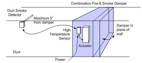
Figure 1 shows (from left to right) a duct smoke detector, high temperature switch,[1] and actuated damper. Roughly 80% of fire and smoke dampers are installed this way although the smoke sensing may be via area smoke detection and a relay employed to operate the damper. The damper protects the integrity of the wall to maintain compartmentation so that neither smoke nor fire can pass to an adjacent compartment.
Figure 1 Typical installation of a combination fire and smoke containment damper.
Figure 2 shows the wiring. Starting at the far left, hot power is run to the smoke detector. As long as smoke is not present the detector passes power to the temperature switch. Power to the actuator drives the damper open and holds it in the open position.
If smoke is detected power is removed from the actuator and the alarm contact on the detector closes to issue an alarm. If an area smoke detection system is used, the smoke control system has a relay connected in place of the smoke detector contact.
In case smoke is not detected but the temperature at the damper rises to 165°F (74°C), then the temperature responsive switch opens. This cuts power to the actuator and the damper springs closed. The temperature switch is manual reset so the damper remains closed during the event.
In the cases where the damper is only a smoke damper, the temperature switch is not present. The smoke detector or a relay from the smoke control system is the only operating control. 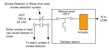
Figure 2 Smoke detector and combination fire and smoke damper wiring.
Engineered Smoke Control System Dampers
Roughly 80% of fire and smoke dampers are installed in containment applications as shown above. About 20% are installed in more customized applications that are designed by the fire protection and mechanical engineers. Typical applications are atria, stairwell pressurization systems, underfloor air conditioning, underground floors, and large spaces like malls, auditoriums, and stages.
Figure 3 shows the basic controls employed in a smoke control system for one damper. The Fire fighters’ Smoke Control System (FSCS) panel allows override control and provides status indication for all components of the system. 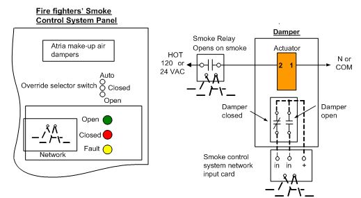 Figure 3 FSCS panel and remote smoke damper wiring.
The dampers used for smoke control are typically of the same construction as containment. The primary difference is in the control methods. The damper blade position indication switches may be auxiliary switches on the actuator, damper blade switches, or magnetic contact switches. The smoke control system has a relay that allows the FSCS panel switches to place it in automatic, closed, or open position. Figure 3 also shows the connections to a networked system. The relays or cards are isolated from the line or 24V power used to operate the actuator.
The smoke control system components are UL 864, UUKL listed. The actuator has UL 873 or UL 60730 electrical listing and UL 2043 low smoke generation listings. The damper and actuator as a unit is UL555S listed.
Figure 4 shows a reopenable damper. Wiring for the Auto-Off-On Override switch is shown connected directly to the FSCS panel although typically there are network relays present to perform the functions. This damper serves both in containment and smoke control functions. It is connected to the FSCS panel so that the fire department incident commander can reopen the damper to remove smoke or pressurize a space. Status indication is provided. 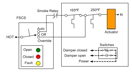
Figure 4 Reopenable damper.
Sequence of Operation
In Automatic mode the smoke relay responds to the programming of the control panel to cut power and spring the damper closed when appropriate. Alternately, if a fire is present and the temperature in the duct rises to 165°F (74°C) the primary temperature switch opens and the damper springs closed.
If the panel switch is moved to Override, then the smoke relay and primary sensor are bypassed. The actuator is again powered and the damper opens. However, if the temperature at the damper continues to rise then the secondary sensor opens at 250°F (121°C). (The fire is close enough that there is danger of flames or heat moving through the damper to the other side of the wall.)
In addition, if the fire department moves the switch on the FSCS panel to Off, then power is removed from the actuator and the damper closes.
Modulating Control System Dampers
Some systems require proportional control of the dampers in the fire and smoke applications discussed above. The controls must combine typical temperature and/or pressure control methods as well as fire and smoke functions.
Figure 5 shows the simplest of modulating control methods for a fire and smoke damper. It is used commonly for corridor ventilation. The potentiometer sets a balance position for the damper during normal operation. The relay can close the damper in event of fire avoid smoke spread.
Power is placed on the actuator terminals 1 and 2. The potentiometer has a varying signal of from 2 to 10VDC that goes to terminal 3, the signal input. The actuator positions from 0 to 100% to open the damper to the balanced position. The common acts as a source of electrons and carries both AC and DC currents. In an event, the Override relay can cut power to the actuator which then springs the damper closed.
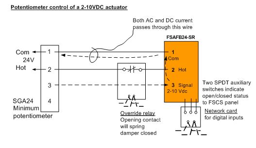
Figure 5 Potentiometer control of a smoke damper with override closed.
Figure 6 shows the same smoke damper as in Figure 4 with an added relay to override the damper open. By shorting hot power to terminal 3 of the actuator, it will drive open. While not always necessary, a contact opens to disconnect the signal terminal on the potentiometer. This prevents hot 24VAC from damaging the signal output. On DDC systems this is important.
There are optional wiring configurations that work just as well as that shown. For example, Override relay 2 could be placed in the common 24VAC wire. At times it is important to arrange the relay contacts so that in case of failure of one relay, the failsafe condition is the safest.
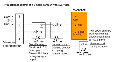
Figure 6 Potentiometer control of a smoke damper with override open or closed
In Figure 7 instead of a minimum potentiometer controlling the actuator, a building automation system, direct digital control sends the signal to terminal 3 and the actuator is continuously adjustable. (Default is 2V, closed and 10V, full open. This is reversible when needed for some applications.) The signal path is from Sig + on the controller to 3 through the actuator electronics to 1 and back out to the controller Com. A complete loop is always needed for current flow out and into any device.
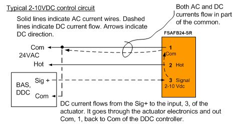
Figure 7 Typical analog 2-10VDC actuator control circuit.
Figure 8 adds a high temperature switch. It is shown here in the common wire, but could be placed in the hot wire also. If the temperature at the damper rises to 165°F (74°C) the switch opens to cut power to the actuator and it springs the damper closed.
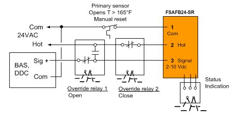
Figure 8 Control of a fire and smoke damper showing high temperature switch.
Normally, the damper modulates based on the output signal from the BAS controller. Typically, if smoke is detected, the automatic response is to make Override relay 2 and spring the damper closed. If the FSCS panel is set to Open, then Override relay 2 is de-energized and Override relay 1 is energized. The damper is then open 100%. However, if the temperature in the duct going into the damper reaches 165°F (74°C), then the damper again closes.
Figure 9 adds a secondary high temperature switch and a bypass relay in the common wire.
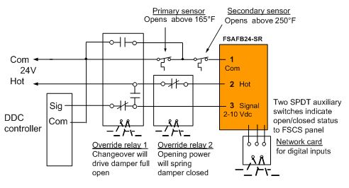
Figure 9 Reopenable combination fire and smoke damper.
The sequence of operation is as follows:
With 24VAC present and all controls in the normal[2] state, the actuator opens damper to the position the Signal indicates. Actuator will modulate to maintain the setpoint.
Cutting 24VAC power or making Override relay 2 closes the damper.
If the temperature at the damper reaches 165°F (74°C), the primary sensor opens and the damper springs closed.
If the FSCS panel switch is set to Open, several actions occur.
a. The primary sensor is bypassed reconnecting the common power to the actuator.
b. Override relay 1 is made and Override relay 2 goes to normal. This causes the actuator to drive full open. (Hot 24VAC is shorted to the actuator terminal. Hot 24VAC is not allowed to reach Signal of DDC controller as that would destroy the output’s electronics.)
However, if the duct temperature reaches 250°F (121°C), then the secondary temperature switch opens and the damper again closes. The FSCS panel cannot override this and manual reset is necessary. It is presumed that the fire is too close to the damper and compartmentation is at risk.
Underfloor Air Conditioning Example
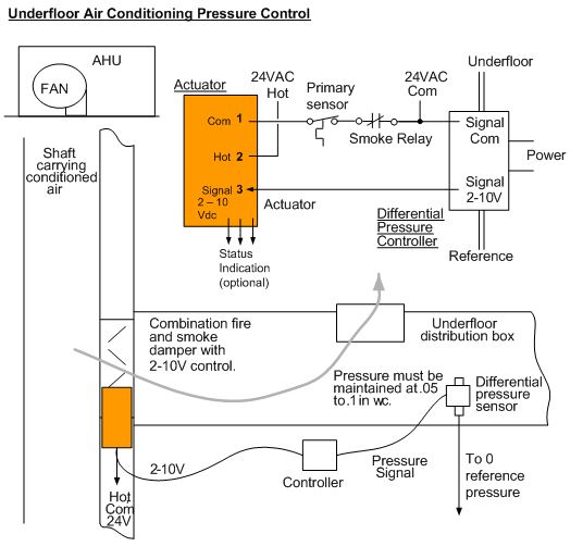
Figure 10 shows an example of an underfloor air conditioning system and how a modulating actuator could function.
The shaft wall is a fire barrier and a smoke partition and therefore requires either separate dampers or a combination fire and smoke damper. The pressure under the floor must be maintained at somewhere between 0.05 and 0.10 in. w.c. (12 to 25 Pa). This would require another damper and modulating actuator. However, by using a modulating fire and smoke damper, only one damper and actuator can do the job of three. This saves material and labor costs and also helps alleviate space constraints.
Figure 10 Underfloor air conditioning example.
It would be up to the fire protection engineer and the local authority having jurisdiction to determine if this damper is considered part of containment (Chapter 7) or part of the engineered smoke control system (Chapter 9). It could be used for both. If it is part of the smoke control also, then status indication and overrides would be required.
The sequence of operation is:
- During normal operation the pressure under the floor is maintained by modulating the damper mounted in the shaft wall.
- If a fire occurs and the temperature at the damper reaches 165°F (74°C), then the damper closes.
- If smoke is present in duct (or space area), then damper closes.
Summary
There are a large number of methods to modulate fire and smoke dampers and apply fire and smoke safety controls. In containment applications, the damper is closed when either high temperatures or smoke is observed. In smoke control systems a number of ways exist to either open or close the damper to purge or pressurize spaces to prevent smoke from spreading.
Some, not all, of the methods of control are shown and explained in this article. Consult the referenced Codes and Standards or contact the author for additional information.
Author - Larry Felker
Larry Felker is a mechanical engineer and member of ICC (International Code Council), NFPA (National Fire Protection Association), and a life member of ASHRAE (American Society of Heating, Refrigeration Air Conditioning Engineers). He is a Product Manager for Fire & Smoke Actuators for Belimo Americas who has specialized in fire and smoke dampers and actuators since 2002. Previously he was a temperature control system designer and before that a mechanical and electrical contractor. He is the co-author (with Travis Felker) of Dampers and Airflow Control, ASHRAE Special Publications, 2010, and authored a white paper on Actuator Dampers in Smoke Control Systems.
References
(IBC) International Building Code, 2012, International Code Council, Inc. (ICC), Country Club Hills, IL 60478-5795
(IFC) International Fire Code 2012, ICC, ibid.
(IMC) International Mechanical Code 2012, ICC, op. cit.
UL 555 Standard for Safety for Fire Dampers, Edition 7, 2006, Updated 2010, Underwriters Laboratories Inc. (UL), 333 Pfingsten Road, Northbrook, IL 60062-2096
UL 555S Standard for Safety for Smoke Dampers, 4th Edition, 1999, Updated 2012, ibid.
UL 864 Standard for Safety Control Units and Accessories for Fire Alarm Systems, 9th Edition, 2010
UL 873 Standard for Temperature-Indicating and -Regulating Equipment (Ed. 12), U, 2007
UL 2043 Fire Test for Heat and Visible Smoke Release for Discrete Products and Their Accessories Installed in Air-Handling Spaces, Standard 2043, Edition 4, 2013
UL 60730 Standard for Automatic Electrical Controls for Household and Similar Use, 2010
[1] “Primary heat responsive device” in UL 555 terminology.
[2] “Normal” is defined as the de-energized or low variable condition. For example, low smoke is the normal condition.