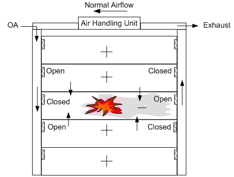
There are any number of applications where a new type of actuator allows slick methods of control while saving money and space at the same time; this is just one. Figure 1 depicts the corridors in a building with a fire on the middle floor. In normal operation, the corridors are pressurized with a mixture of conditioned and outside ventilation air. Some of the return air exhausted to remove stale air. Since the ducts are within fire and smoke barrier walls, a fire and smoke damper is required where the ducts pass through the walls. In addition, in order to balance airflow quantities, balancing dampers must be installed at the take-offs. The dampers are closed part way to adjust the air flow differences. However, in event of a fire, the operation changes.
 In event of a fire the corridors are used to allow occupants to exit the building; the corridor must be kept free of smoke. If there is a fire on the floor, then the supply damper closes and the exhaust opens fully. Smoke is pulled out of the corridor so that occupants can escape. This is shown in Figure 2.
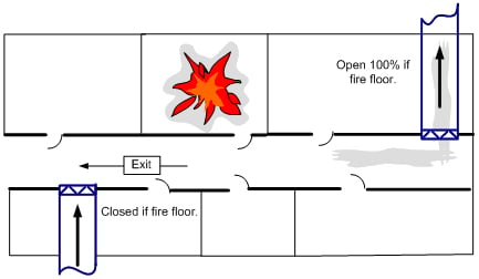 Figure 2. Corridor dampers and application.
The actuators are balanced by the TAB (Test, Adjust, and Balance) contractor and the controls contractor so that the right amount of air enters each floor in normal operation. The dampers are sized so that when full open they pull sufficient air out of the corridor.
Figure 3 shows a typical damper and the actuator wiring.
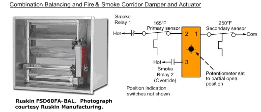
Figure 3. An actuated balancing fire and smoke damper.
The actuator is a 3-position actuator. It has a potentiometer on the face which allows setting the maximum normal amount it will open.
In normal operation the actuator drives the damper open to the position to which the potentiometer is set. The balancer adjusts the potentiometer to get the required normal ventilation supply airflow. This is performed at both the supply and return dampers.
If a fire or smoke is detected on any other floor, then the Smoke Relays at the supply damper do not change over and the damper stays open. At the exhaust damper, the Smoke Relay 1 is powered and the contact opens. The damper then springs closed. Since there is no exhaust, this corridor is pressurized. Smoke cannot enter the floor and obscure vision of the occupants while they exit.
If the fire is on the dampers’ floor, the opposite happens. At the supply damper, Smoke Relay 1 opens and the damper closes. At the exhaust damper, Smoke Relay 2 closes its contacts and bypasses the potentiometer. The actuator drives full open to make the corridor negative in pressure and to exhaust smoke. Regardless of the position of Smoke relay 1 or the thermal sensor, powering wire 3 drives the damper 100% open.
If the fire is right at the damper, the primary sensor opens up at 165ºF. The exhaust damper closes. This prevents fire from entering the shaft. If, however, the actuator is connected to the Firefighters Smoke Control System (FSCS) panel, the switch on the FSCS panel is set to Open, then Smoke Relay 2 closes and the damper again opens. But again, if the fire is intense or close enough to reach 250ºF at the damper, then the secondary sensor opens and the damper closes. Both sensors are manual reset.
Go to www.belimo.us/firesmoke for further information, located in n the documentation and pricing section, click the FSAF24-BAL for a technical submittal.