Introduction
The International Building Code and the NFPA standard requires that all fire and smoke dampers be tested regularly. But in practice, not all dampers are so easy for technicians to get to.
The International Building Code (IBC) Section 717.4.1.2 Ducts and Air Transfer Openings states:
Restricted access: Where space constraints or physical barriers restrict access to a damper for periodic inspection and testing, the damper shall be a single- or multi-blade type damper and shall comply with the remote inspection requirements of NFPA 80 or NFPA 105.
NFPA 80 (fire) Section 19.5.2.3.3 Remote Inspection Method and NFPA 80 (smoke) Section 7.5.2.3.3 Remote Inspection Method give the same requirements:
a. A damper with remote inspection capability shall positively indicate when the damper is fully open and fully closed
b. The initial remote inspection shall be visual
c. The initial inspection shall confirm that the position indication method accurately reflects the full-open and full-closed positions of the damper
Although the exact methods of inspection to be used are not specified in the code, considering current technology and cost effectiveness trends, the use of indicating switches is to be assumed. But, other inspection methods are possible and may be used in the future. For example, cameras, sonic sensors, or airflow switches could be employed. In any case, only actuated dampers can be tested remotely, as the damper must change positions. On the other hand, curtain fire dampers must be manually tested. Thus, if the damper location is inaccessible, an actuated fire damper must be installed instead of a curtain type damper.
The required testing frequency for fire and smoke dampers is every 4 years in commercial buildings and every 6 years in hospitals. Figure 1 illustrates the types of life safety dampers employed in the Americas.
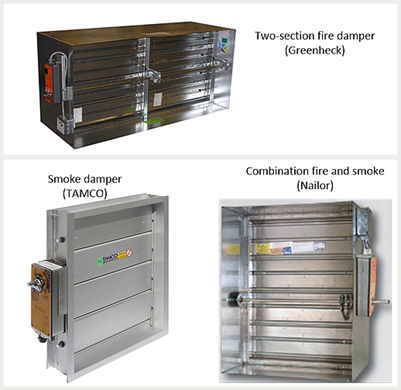
Figure 1 The basic types of actuated life safety dampers
(Photos courtesy Greenheck, TAMCO, and Ruskin)
IBC Chapter 9 Smoke Control Systems
IBC Chapter 9 defines requirements for smoke control systems. The dampers employed in them must be connected to the firefighters‘ smoke control system (FSCS) panel. This is often a combined fire alarm and smoke control panel, and position indication and override control are required. These systems have been in operation since the 1980s using hardwired connections and, in recent years, using proprietary network communications. This is exemplified in Figure 2. The wiring connections are the same as those shown in Figure 4 below.
Since smoke control dampers are always connected to a central control panel, Section 717.4.1.2 does not apply. All smoke control system dampers can be tested remotely, whether accessible or not. Some are automatically tested weekly per NFPA 105 and NFPA 92 requirements. The interface modules for smoke control are UL 864 UUKL listed, while Chapter 7 damper testing modules only need UL 60730.
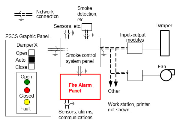
Figure 2 Smoke control system with proprietary input-output modules
IBC Chapter 7 Containment Dampers and Control
Some 90% of smoke and combination fire and smoke dampers are installed to meet Chapter 7 requirements. These dampers are always actuated since there is no mechanical way to sense smoke; thus electronic methods are necessary. This includes corridor dampers, which are combination dampers with unique sleeves for in-ceiling mounting.
These dampers are not connected to the FSCS panel. They are most often located in a barrier wall with a duct smoke detector and a high ambient limit controlling them. In some cases, an area smoke detection system is used with a relay contact from the fire alarm system wired in series with the high limit and actuator. The smoke detector is wired to the fire alarm system, but the damper itself is free-standing.
Figure 3 Shows the most common control method for a combination fire and smoke damper. A smoke damper would not have a high-temperature limit on the damper ; otherwise, the units are identical.
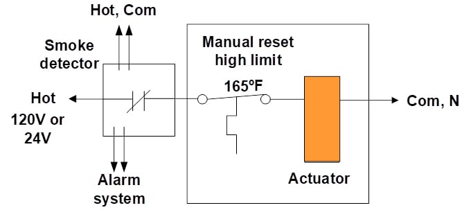
Figure 3 Standard duct smoke detector and combination fire & smoke damper
Remote testing panels have been provided by damper manufacturers for over 25 years and by fire alarm companies back into the 1980s. Figure 4 shows a typical test panel and damper with auxiliary switches. The auxiliary switches can be magnetic, self-contained in the actuator, attached directly to a damper blade, or axle shaft mounted. Fire and smoke dampers may be factory ordered with blade position indicating switches or actuator auxiliary switches.
Since all containment dampers fail close, power passes through the momentary test switch to the actuator, which drives the damper open. Once the damper is fully open, the position switch is closed, and the green light is illuminated. When the momentary test switch is depressed, the actuator springs the damper closed and illuminates the red light. Upon release of the momentary test switch, the actuator drives the damper back open, and the green light is again illuminated. This completes the remote test.
The test panel is typically located on an adjacent equipment room wall or in close proximity to the damper that it controls. If it must be located in an area accessible to the public, a keyed switch is provided. Toggle switches are also available.
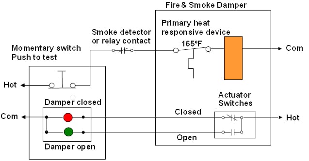
Figure 4 Momentary test switch and indicator lights
The periodic testing is the same as that provided by a remote panel. It requires that power be cut to the damper actuator, which then springs the damper closed. The technician confirms that the damper closes and reopens. While the test is quick, finding the damper, setting up a ladder, covering up furniture and equipment from falling debris, opening a ceiling tile, finding the access door, closing up the ceiling tile, and cleaning up can be time-consuming.
Central control can be provided by the use of a proprietary fire alarm panel, a smoke control system, or a standard building management system (BMS). Damper connection can be made with proprietary input-output modules or BACnet testing modules. BACnet is standard in the HVAC industry.
Currently, precise terminology has not been standardized throughout the industry. There are “local remote“ test stations or panels as described above. Then there are “centrally connected remote“ test modules. These are similar to the smoke control system modules, shown in Figure 2, and the BACnet modules, shown in Figures 5 and 6. They require the installation of a test module and using position indicating switches or actuator auxiliary switches to allow the damper to be tested from a central location. A BACnet testing module can be applied, as shown in Figure 5. Details of the wiring are shown in Figure 6.
Note: In all cases, the existing safety controls (smoke detector &/or high temperature limit) are never bypassed and are always in the circuit.
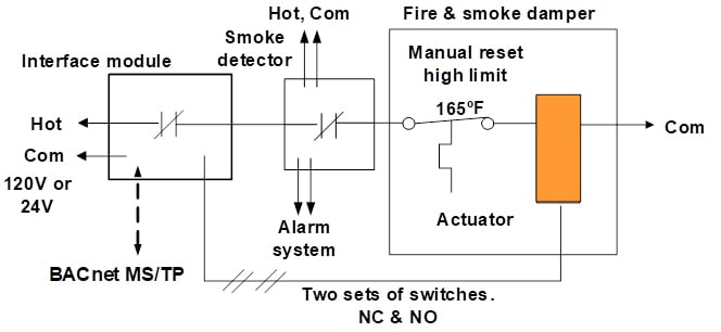
Figure 5 Testing module installed with a standard combination fire and smoke damper
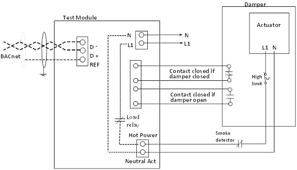
Figure 6 Wiring details for a BACnet damper testing module
BACnet Control
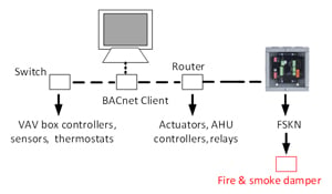
Although fire alarm and smoke control panels have BACnet capability, it is normally only used to communicate with BMS central controllers. More commonly, BACnet is used for building management systems and energy management. Figure 7 shows a simplified system with a central computer with connections to peripheral devices.
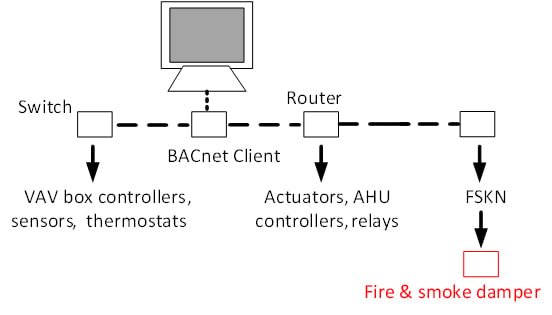 Figure 7 Basic BACnet network system
BACnet MS/TP uses a multiconductor RS-485 cable wired in daisy-chain topology. Figure 8 shows the power and RS485 network wiring for a typical device.
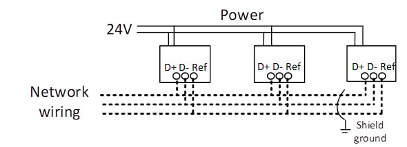
Figure 8 Power and RS 485 wiring to remote modules
BACnet Programming
Typically, the baud rate, parity, and address of devices are set with dip switches on the interface. The BACnet protocol features device discovery, which allows the operator to poll the networked devices for their identifying information and operational status and values.
The BACnet programmer will set the address of the module, per the BACnet standard requirements. The status of the device itself and the damper it controls can be checked with one or two commands. The programmer sets up a “Test” command, which is sent out to each module on the network, and “success” or “failure” is reported. If a device failed, it can appear in an exception report and it can be retested after repairs are made.
Summary
As stated, the IBC Section 717.4 requires remote testing capability for any fire and smoke damper that is inaccessible for manual testing.
The building and fire codes require periodic testing of fire and smoke dampers. The codes reference NFPA 80 and NFPA 105 for details on inspections and maintenance. Commercial buildings must be tested every 4 years, and hospitals must be tested every 6 years, although some local codes, and all Canadian codes require testing annually.
Most testing can be performed manually by a qualified individual, but some jurisdictions require a certified technician. Testing can also be performed by using a remote testing module. Smoke control system dampers (IBC Chapter 9) are currently required to have interface modules, which can be utilized for automatic periodic testing. Containment dampers (IBC Chapter 7) can be connected to a BACnet control network to perform tests using auxiliary switches to confirm open and closed.
BACnet is the standard network control protocol for HVAC systems and is well-suited for remote testing.
(i) International Building Code, 2021 edition, International Code Council, Inc. (ICC), Country Club Hills, IL 60478-5795. www.iccsafe.com
(ii) NFPA 80 Standard for Fire Doors and Other Opening Protectives, 2022 Edition, National Fire Protection Association, 1 Batterymarch Park, Quincy, MA 02169-7471. www.nfpa.org
(iii) NFPA 105 Standard for the Installation of Smoke Door Assemblies and Other Opening Protectives, 2022 Edition, ibid.
(iv) NFPA 92, Standard for Smoke Control Systems, 2021 Edition. NFPA, op. cit.
BACnet, A data communications protocol for building automation and control networks.
(v) ASHRAE, 180 Technology Parkway NW, Peachtree Corners, GA 30092.