Periodic testing of life safety systems and dampers is required by the International Building Code (IBC)1, and the International Fire Code (IFC)2 . There is some state and local variation to the testing, but the general requirements specified in the codes are shown in Chart 1. While the focus of this article is on dampers themselves, the entire smoke control system requires testing according to the schedule labeled “Smoke Control Systems & Dampers” from Chapter 9 of the IBC. A clear distinction must be made between damper applications in order to determine the appropriate code schedule. The second part of this article explains these differences.

Codes and Referenced Standards
Chart 1 draws from the IBC and the IFC. It is the IFC that defines or references most testing requirements. It references NFPA 803 (fire) and NFPA 105 4 (smoke) directly for the containment damper requirements. These two standards provide details on what to test or inspect, periodic requirements, and replacement information. While the IBC is generally used for the smoke control system as a whole, the IFC provides smoke control system requirements directly – 909.20.4 for dedicated systems and 909.20.5 for non-dedicated systems. NFPA 90A5 , NFPA 926 and NFPA 803 are also frequently referred to with respect to testing. However, they are not referenced by the IBC or IFC, and only apply to smoke protected seating, as outlined in NFPA 101, the Life Safety Code.8
How often is periodic testing required by National Fire Protection Code 80 and 105?Both standards state the requirement for testing is one year after installation and then every 4 years (hospitals every 6 years). Chapter 6: Installation Testing, and Maintenance of Smoke Damper is the most important chapter with respect to testing smoke and combination dampers. |
Dampers Required by Chapter 7 of the IBC
Chapter 7 of the IBC regulates fire resistant rated construction. Fire dampers are installed in firewalls, fire barriers, fire partitions, and horizontal assemblies. Smoke dampers are installed in smoke barriers and smoke partitions. Combination fire and smoke dampers that are required by Chapter 7 can be installed in any of the applications that require both fire-rated construction and smoke containment. They are meant to resist the passage of flames and smoke particulates.
Most fire dampers have fusible links that melt at (typically) 165°F (74°C) allowing gravity or a shaft spring to close the damper. Fire dampers are rarely actuated in the Americas (although they are regularly actuated in Europe so that they can be tested automatically). See Figure 1 for a typical curtain fire damper. There are several variations, and ceiling dampers are similar.

A typical smoke damper is actuated and connected to a duct smoke detector or to a relay from the fire alarm or smoke control panel. If smoke is detected, the actuator closes the damper, preventing smoke movement from one area to another.
A combination fire and smoke damper looks similar to a smoke damper but is equipped with a high-temperature sensor to close the damper in addition to the local smoke detector.

Combination fire and smoke dampers can be controlled in several ways. Most modern dampers commonly use an electronic temperature activated sensor-switch. When the contacts are closed, the actuator is powered and drives the damper open. When fire or heat is detected, the contacts open and the damper shuts. See Figures 3 and 4.
In addition, a smoke detector or relay contact from the area smoke detection system panel is wired in series with the temperature switch. If smoke is detected, the contact opens, and the actuator springs the damper closed. See Figure 3. The wiring for the typical combination damper is shown in Figure 4.
Though not required by Chapter 7, in order to automatically test these dampers, position indication switches may be installed. These position switches can trigger monitoring lights or indicate their position to a testing panel over a network. These dampers are best described as containment or compartmentation dampers, as that is their primary function, clearly distinguishing them from the smoke control dampers discussed below. Often called “passive” protection, they are active in that they close openings in fire or smoke walls, barriers, and partitions.


Dampers required by Chapter 9 of the IBC
IBC Chapter 9, Fire Protection Systems, regulates the installation of engineered smoke control systems (as well as alarms and sprinklers). Dampers, fans, architectural reservoirs, and smoke chimneys may be employed in order to remove smoke or prevent the movement of smoke into protected spaces. These are considered active systems.
Smoke control systems are required in occupancies such as atria, stairwells, underground buildings, and large spaces like malls and auditoriums. Some local codes also require additional protection in corridors and any exit passages.
Most smoke control dampers are constructed similarly to containment dampers. Some smoke dampers are made of aluminum, while fire and smoke dampers are typically galvanized or stainless steel. The control capabilities of smoke control damper systems, however, are more sophisticated, allowing for the coordination of alarms, sprinklers, fans, doors, and dampers. The containment damper is closed by only a local duct smoke detector, or in the case of the combination fire and smoke damper, by the detector or a single high-temperature sensor. The detector can be mounted at the factory or field installed, but UL555S requires that the sensor and actuator be factory installed.
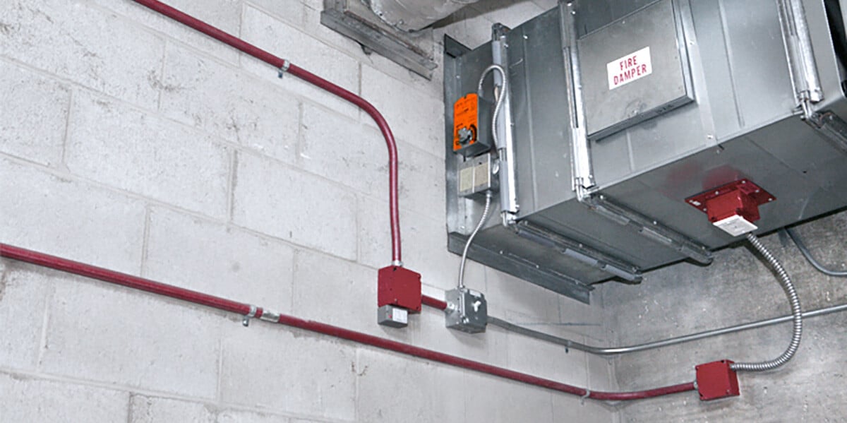
In particular, smoke control dampers are connected to the firefighters’ smoke control system panel for manual override control and position indication and verification. These dampers are often referred to as “re-openable” since they can be manually opened or closed, although they are normally in automatic mode. See Figure 5 for an example. Figure 6 shows the full wiring for override and position indication. Note that modern systems typically use a network for the long wire runs. For this example, discrete wiring is shown.


In addition to distinguishing between Chapter 7 and Chapter 9 dampers, there are two types of smoke control system dampers to consider – dedicated and non-dedicated. A dedicated system is used for no other purpose than smoke control. For example, an atrium make-up air damper and atrium smoke exhaust fan damper are not used in day-to-day operation. A non-dedicated system is used for normal HVAC or ventilation and is operated on a regular basis. If it fails, it would require immediate repair. Failure of dedicated system dampers will not be evident without operation, so they must be tested more frequently to ensure safety.
Testing procedures
Other than stating that both initial and periodic inspection and testing of dampers are required, the codes do not detail the steps that need to be taken. However, the intent is clear – compliance with NFPA 80 and NFPA 105, as well as with damper manufacturer requirements, are expected.
In NFPA 80, section 19.5.2.3 “Periodic Testing for Dampers That Do Not Use a Fusible Link to Operate”, fire damper testing is detailed. The essential test is that the damper will open and close, and that no obstructions are present. There are two methods for performing this test, the visual inspection method and the remote inspection method.
NFPA 729 is applicable when any smoke detection is present. The operation must be under the airflow conditions that the system will encounter. Fusible links must comply with NFPA 90A and UL33.10 Any reported deficiencies and/or recommended corrective actions must be documented. It also states that “repairs shall begin without delay,” and that the repairs must be tested once completed.
Both standards state that testing is required one year after installation and then every four years (six years for hospitals).
NFPA 105 is worded very similarly to NFPA 80 and contains many of the same requirements, which can be found in section 7.5.2 “Periodic Testing.” An operational test is required upon installation, and testing can be done using the visual or remote inspection methods. NFPA 92A is referenced for periodic inspection and testing. Repairs must “begin as soon as possible” and all maintenance must be documented.
In today’s ever-changing world, it is important to highlight the remote inspection method. This method was added to the NFPA standards in 2018 and provides a more realistic way to comply with the burden of testing. Due to the need for periodic testing and the difficulty in accessing life safety equipment in many buildings, the ability to remotely test these dampers or schedule automated tests through a Building Management System (BMS) can enhance building safety and save lives.

In Figure 7, Belimo’s Remote Inspection Module, the FSKN, is used to provide a connection between the BMS using BACnet (or Modbus) and the actuator. When a test command is sent, the actuator cycles from fully open to fully closed and back again, as required by the standards. A test completion message, indicating either PASS or FAIL, is then sent back to the BMS for logging and auditing purposes. When a remote inspection fails, a visual inspection is then required to complete the test. Remote inspection offers many benefits, such as enabling the testing of inaccessible dampers and avoiding the disruption of containment in hospitals. It is particularly useful for large campuses with many dampers, helping to reduce costs by utilizing the BMS and existing on-site staff. Given these advantages, remote inspection should be considered in the design and planning of new systems or retrofits.
Many people are often confused or hesitant to touch or change a life safety damper, leading to uncertainty when repairs are needed. Misinterpretation of UL555(S) standards can hinder simple repairs or upgrades to existing systems. UL555 (fire) and UL555S (smoke) certifications apply to dampers and their installed components, such as smoke detectors and actuators. It is essential to remember that any time a damper is being installed, compliance with UL555(S) is mandatory. However, if the damper itself is not being changed, and the issue is due to a component failure, such as a pneumatic actuator, then UL555(S) is no longer relevant. Proper repairs should be made as soon as possible using equal or better components.
Belimo has published instructions for installing replacement actuators on dampers12. These instructions include a form to leave on site for the fire marshal or building official, in compliance with the documentation requirements of NFPA 80 and NFPA 105. The instructions focus on obsolete actuators from the 1980s up to the present. Often, the dampers themselves are in perfect condition, with only one or more electrical components being defective.
Summary
The first step in establishing a periodic testing schedule for dampers is to identify whether they are employed for Chapter 7 or Chapter 9 code requirements. Once that is achieved, operational testing itself is straightforward. To what extent manual inspection is required for smoke control dampers is up to the local inspector. Since smoke control dampers have blade switches or their actuators have auxiliary switches, a test of the entire smoke control system will test the dampers and position indication is automatically shown on the fire fighters’ smoke control panel.
__________________________________________________________________________
1International Building Code, 2012, International Code Council, Inc., Country Club Hills, IL 60478-5795.
2International Fire Code 2012, ibid.
3NFPA 80 Standard for Fire Doors and Other Opening Protectives, National Fire Protection Association, NFPA, 1 Batterymarch Park, Quincy, MA 02169-7471.
4NFPA 105 Standard for Smoke Door Assemblies and Other Opening Protectives, ibid.
5NFPA 90A Standard for the Installation of Air-Conditioning and Ventilating Systems, op.cit.
6NFPA 92 Standard for Smoke-Control Systems, op.cit.
8NFPA 101 Life Safety Code, National Fire Protection Association, op.cit.
9NFPA 72, National Fire Alarm Code, op.cit.
10UL 33, Standard for Heat Responsive Links for Fire-Protection Services, Underwriters Laboratories Inc. (UL), 333 Pfingsten Road, Northbrook, IL 60062-2096.
11 Air Movement and Control Association International, Inc. 30 West University Drive, Arlington Heights, IL 60004-1893 U.S.A.
12https://www.belimo.com/us/en_US/products/retrofit/product-documentation/fire-and-smoke-damper-actuator#replacement-solutions BELIMO Automation AG.