One of the main features of the BACnet protocol is a service called device discovery. This service allows the Building Automation System (BAS) operator to poll the networked devices for their identifying information, operational status, and values. Devices are identified by their device object name and unique instance number (ObjectID). A device name is optional, while the ObjectID serves for the controls to identify devices. Unlike all other object types, each device may contain only one Device object. The instance number of this Device object must be field-configurable so that it may be assigned a unique instance number among all of the Device objects of all of the devices on a given BACnet internetwork.
Additionally, a field may exist for the location in the building or on the network. These can also be recorded in programming notes and do not necessarily reside on the module. A password is another feature that may exist but is not critical to function.
When setting up the Energy Valve for BACnet communications, either BACnet MS/TP or BACnet IP must be chosen based on the desired BACnet network topology. In addition to this setting, the Energy Valve must be assigned a unique Instance ID. Using BACnet MS/TP, the user must choose the appropriate baud rate and MAC address. It is advisable, but not necessary, to set the Max Master to that of the BAS network on which the EV is being installed. Using BACnet IP, the user will have to assign a UDP port. This port should default to 47808 but must match the port used by the BAS system. Entering a device name that describes the EV location is also a good practice.
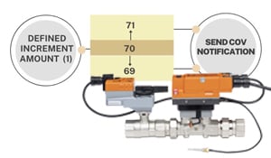
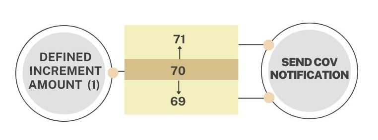
After device discovery is performed, the next task is integrating object data to exchange and report information between devices. There is a lot of information, and values don't frequently change in many cases. Most BASs' monitor data object values by continuous polling, which wastes network bandwidth by increasing network traffic. Change Of Value (COV) schemes are one way to mitigate this traffic. A COV involves the client subscribing to the server device containing the value of interest and specifying the change amount. After the subscription is accepted, the server device monitors the object's value. The server issues a COV notification if the value has changed by more than the defined increment amount since the last reported value. Only values that exceed the defined COV increment get reported, saving network bandwidth by decreasing traffic.
The Belimo Energy Valve™ supports up to six active BACnet COV data subscriptions, in which the client subscribes for notifications from the server with a lifetime of 1… 28'800 seconds. Below is a list of available object values for COV subscription.
BACnet Object Description
|
Object Name |
Object Type |
Description Comment Status_Flags |
Values |
COV Increment |
Access |
|
Device |
Device [Inst.Nr] |
|
0… 4'194'302 |
– |
W |
|
RelPos |
AI[1] |
Relative Position in % |
0...100 |
0.01...100 |
R |
|
SpAnalog |
AI[6] |
If SetpointSource MV[122] is not 1: Analog then Out_Of_Service is TRUE |
0...100 |
0.01...100 |
|
|
Sens1Active_Volt |
AI[20] |
Sensor 1 as Voltage in V |
0...15 |
0.01...15 |
R |
|
Sens1Passive_ Ohm |
AI[21] |
Sensor 1 as Resistor in Ohm |
0.1... 1'000'000 |
0.1... 1'000'000 |
R |
|
T1_UnitSel |
AI[22] |
Temperature 1 (remote) in selected unit |
-20…120 |
0.01…252 |
R |
|
T2_UnitSel |
AI[23] |
Temperature 2 (Flow Body) in selected unit |
-20…120 |
0.01…252 |
R |
|
SpRel |
AO[1] |
Setpoint Relative in % |
0...100 |
0.01…100 |
C |
|
RelFlow |
AV[10] |
Relative Flow in % |
0…150 |
0.01…150 |
R |
|
SpAbsFlow_ UnitSel |
AV [17] |
Setpoint Absolute Flow in selected unit |
0…1,5*Vnom |
0…1,5*Vnom |
R |
|
AbsFlow_UnitSel |
AV[19] |
Absolute Flow in selected unit |
0…1,5*Vnom |
0…1,5*Vnom |
R |
|
Sens1Temp_ UnitSel |
AV [20] |
Sensor 1 as Temperature in selected unit |
-20…248 |
0.01...252 |
R |
|
DeltaT_UnitSel |
AV[22] |
Delta Temperature in selected unit |
0...140 |
0.01…810 |
R |
|
RelPower |
AV[40] |
Relative Power in % |
0...300 |
0.01…300 |
R |
|
CoolingPower_ UnitSel |
AV[45] |
Cooling Power in selected unit |
0… 74'150'000 |
0.1… 73'361'050 |
R |
|
HeatingPower_ UnitSel |
AV[46] |
Heating Power in selected unit |
0… 74'150'000 |
0.1… 73'361'050 |
R |
|
CoolingEnergy_ UnitSel |
AV[47] |
Cooling Energy in selected unit |
0… 2'147'483'641 |
1…1.35E12 |
R |
|
HeatingEnergy_ UnitSel |
AV[48] |
Heating Energy in selected unit |
0… 2'147'483'641 |
1…1.35E12 |
R |
|
VolumeDecimal_ UnitSel |
AV[50] |
Decimal Number of the Volume_m3 Object |
0.01-0.99 |
0.01-0.99 |
R |
|
Volume_UnitSel |
AV[52] |
Accumulated Volume in selected unit |
0… 2'147'483'641 |
1…4.2E10 |
R |
|
GlycolConcentration |
AV[60] |
Glycol concentration in % |
0…100 |
0.01…100 |
R |
|
Vmin |
AV[90] |
Minimum Flow Limit in % |
0…100 |
0.01…100 |
W |
|
Vmin_UnitSel |
AV[93] |
Minimum Flow Limit in selected unit |
0… 360'000 |
0… 360'000 |
W |
BACnet Object Description
|
Object Name |
Object Type |
Description Comment Status_Flags |
Values |
COV Increment |
Access |
|
Vmax |
AV[94] |
Maximum Flow Limit in % |
0…100 |
0.01…100 |
W |
|
Vmax_UnitSel |
AV[97] |
Maximum Flow Limit in selected unit Unit can be selected with object MV[123] |
0… 360'000 |
0… 360'000 |
W |
|
Vnom_UnitSel R |
AV[100] |
Nominal Flow in selected unit |
0… 360'000 |
0… 360'000 |
R |
|
Pmax |
AV[110] |
Maximum Power Limit in % |
0…100 |
0.01…100 |
W |
|
Pmax_UnitSel |
AV[113] |
Maximum Power Limit in selected unit |
0... 74'150'000 |
0.01… 73'361'050 |
W |
|
Pnom_ UnitSel |
AV[116] |
Nominal Power in selected unit |
0… 21'500 |
0.01… 73'361'050 |
R |
|
SpDeltaT_UnitSel |
AV[120] |
Setpoint Delta Temperature in selected unit |
0…99 |
0.01…99 |
W |
|
SpAbsFlowDeltaT_ UnitSel |
AV[127] |
Setpoint Absolute Flow at Delta T in selected unit |
0… 360'000 |
0… 360'000 |
W |
|
BusWatchdog |
AV[130] |
Timeout for Bus Watchdog in s |
0…3600 |
0.01…120 |
W |
|
ErrorState |
AV[140] |
Error State |
Bit 0: No communication to actuator |
1… 16'383 |
R |
Refer to the Energy Valve Technical Documentation for the energy valve setup instructions.