The West Coast of the United States is known for being ahead of the curve when it comes to energy efficiency. California, Oregon, and Washington in particular, have more aggressive energy efficiency standards than most other parts of the country and the world. These states have implemented rigorous policies and regulations that promote energy efficiency, and the use of clean, renewable energy sources. Because of these measures, the West Coast is widely regarded as a leader in energy efficiency, often signaling policy changes that are eventually implemented in other regions of the country.
“The Seattle Energy Code is very progressive as they move away from all fossil fuels,” says Ken Duncan, Belimo District Sales Manager for Washington, Idaho and Alaska. “The Seattle code prohibits the use of traditional gas-fired boilers in commercial buildings, so the typical mechanical HVAC hydronic systems are beginning to utilize heat pumps and heat recovery chillers to heat and cool buildings. This is a completely different style of hydronic heating system, and it requires properly sized and selected control valves to have a trouble-free mechanical system .”
Because of these stringent rules, the industry is largely moving towards pressure independent systems, “without any 3-way valves in any of the piping,” and “at least one or two bypass valves in the system to maintain minimum flow,” Ken explains. 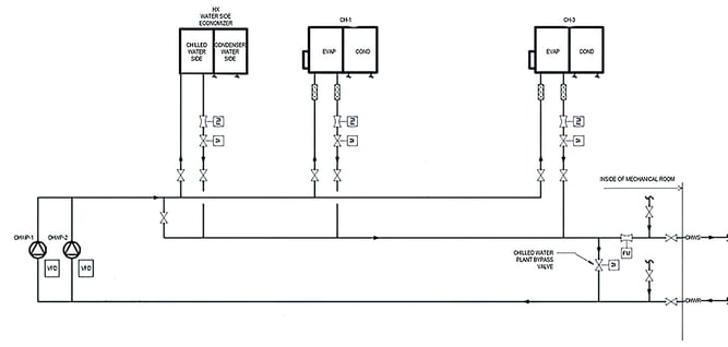
To illustrate this kind of design, the diagram above shows a typical primary pumping system serving two chillers and a water-to-air heat exchanger. When it is cool enough outside, the cooling water is circulated through the heat exchanger and cooled by using the outdoor air instead of using the chillers. This conserves energy and leads to significant energy savings.
If the heat exchanger is unable to accommodate the building’s cooling load, or the outdoor air conditions are unsuitable for “economizer cooling” alone, the chillers will be enabled and staged as needed to meet the cooling demand. As the chillers are placed in operation, the minimum flow rates through each chiller and chilled water distribution pump must be maintained. Since the primary chilled water system does not have a 3-way valve, a bypass valve must be utilized to provide a flow path when the pumps are at minimum speed, and the flow through a single chiller is less than the minimum flow rate for the pump and VFD (variable frequency drive). A primary loop bypass valve ensures that each chiller receives a sufficient minimum flow as they stage on and off or change capacity. This type of primary system typically sees high flow rates and the bypass valve tends to be larger than bypass valves in a secondary system.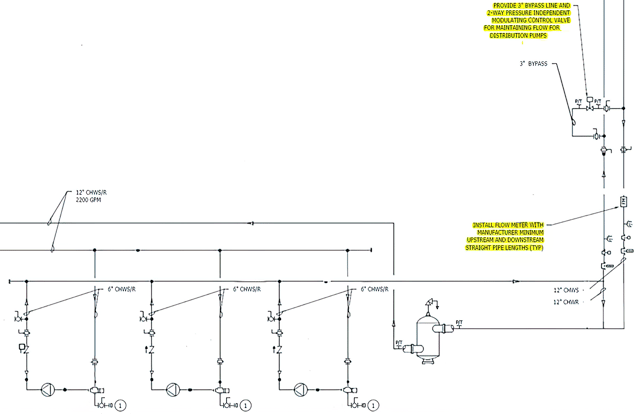
In many buildings, the hydronic system also consists of a secondary pumping system to distribute water to the terminal loads, like the one shown above. Chilled or heated water is pumped out to terminal devices in the building, such as VAV boxes, fan coil units, air handlers and chilled beams.
“The same situation is going to happen here in the secondary system, where we need to maintain minimum flow,” explains Ken. “The two-way valves in the secondary system will at some point be fully closed, and the pumps will have to operate at a minimum speed; this minimum speed corresponds to the minimum flow rate that must be handled by the bypass valve.”
In this kind of design, when all the valves out in the system are closed, the water needs somewhere to circulate. To avoid deadheading the pumps, a bypass line is used to ensure minimum design flow, like the 3-inch two-way pressure independent modulating control valve shown in the upper right corner of the diagram above. This bypass line is typically located somewhere out in the building, far away from the pumps to allow for the overall volume of water in the system to act as a thermal sink, preventing rapid temperature changes to the secondary loop.
A second flow meter in the chilled water return can be seen in the lower right corner of the diagram. The purpose of this flow meter is to measure the flow on the return line, and to communicate with the bypass valve when adjustments to its position are needed to maintain the minimum flow. For example, if the minimum volume of the pumps is 100 gallons a minute, and the system is not achieving 100 gallons per minute on the return line, the flow meter will signal the bypass valve (via the DDC system) to open until 100 gallons per minute is reached.
Bypass Valve Selection
When selecting a bypass valve, it is important to select a valve with a linear flow curve to ensure stable and responsive bypass flow control. Control valves with an equal percentage flow characteristic, on the other hand, are not well suited for bypass flow control. This is because the flow curve is nearly flat in the range between the fully closed position and around 50% open.
As the chart below shows, equal percentage valves do not reach 50% of the rated flow until they are around 70% open. This results in very slow changes to the flow rate when the valve is operating between 0 and 70% open, and once 70% is exceeded, minor changes in valve position greatly affect the volume of water passing through. When equal percentage valves are used for bypass flow control, the control response from the valve is difficult to tune, and usually leads to unstable flow control.
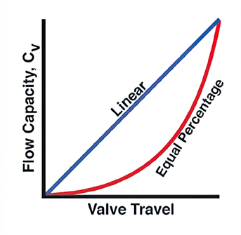
A linear flow characteristic is more suitable for bypass valve applications than an equal percentage curve, because made changes to the position of the valve, will have a linear effect on the flow. So, for example, if the valve is 50% open, 50% of the rated flow will be passed through the valve. This allows for responsive, stable flow control.
The pressure independent Belimo ePIV makes a great bypass valve, as it can be programmed to have either a linear or an equal percentage flow characteristic. Since the flow characteristic is selectable, the valve performs well as a bypass valve or a temperature control valve. The ePIV also features an ultrasonic flow sensor, which allows the actual bypass flow rate to be monitored in real-time. The ePIV is backed by a 5-year warranty.

Are you looking for HVAC training? Belimo offers unlimited access to a library of high-quality, current, and engaging HVAC video tutorials from industry experts. Participants have told us that Belimo training has given them the skills necessary to improve their HVAC skills.