
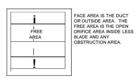
A damper restricts airflow by obstructing the duct. Some multi bladed dampers have flanged frames to which ductwork is butted, and the open area is restricted only by blades and hardware. Most dampers in the U.S. are inserted into a sleeve, duct, or wall, and the frame obstructs part of the open area. The maximum free area for this type is about 80% for 48 x 36 in. (1200 x 900 mm) and larger-size dampers, and the minimum is about 40% for an 8 x 8 in. (200 x 200 mm) damper. The frame takes up most of the reduced space. The free area changes slightly with comer braces, linkage in airstream versus frame, airfoil versus triple V, and with type of frame. In round dampers, the blade is the only significant restriction.
Commercial flanged dampers of the type more commonly used in Europe may have 90% free area, and U.S. insulated blade and industrial dampers may have a maximum of only 70%. Check specifications in all cases. The information in this article is specific to U.S. hat-frame commercial dampers.
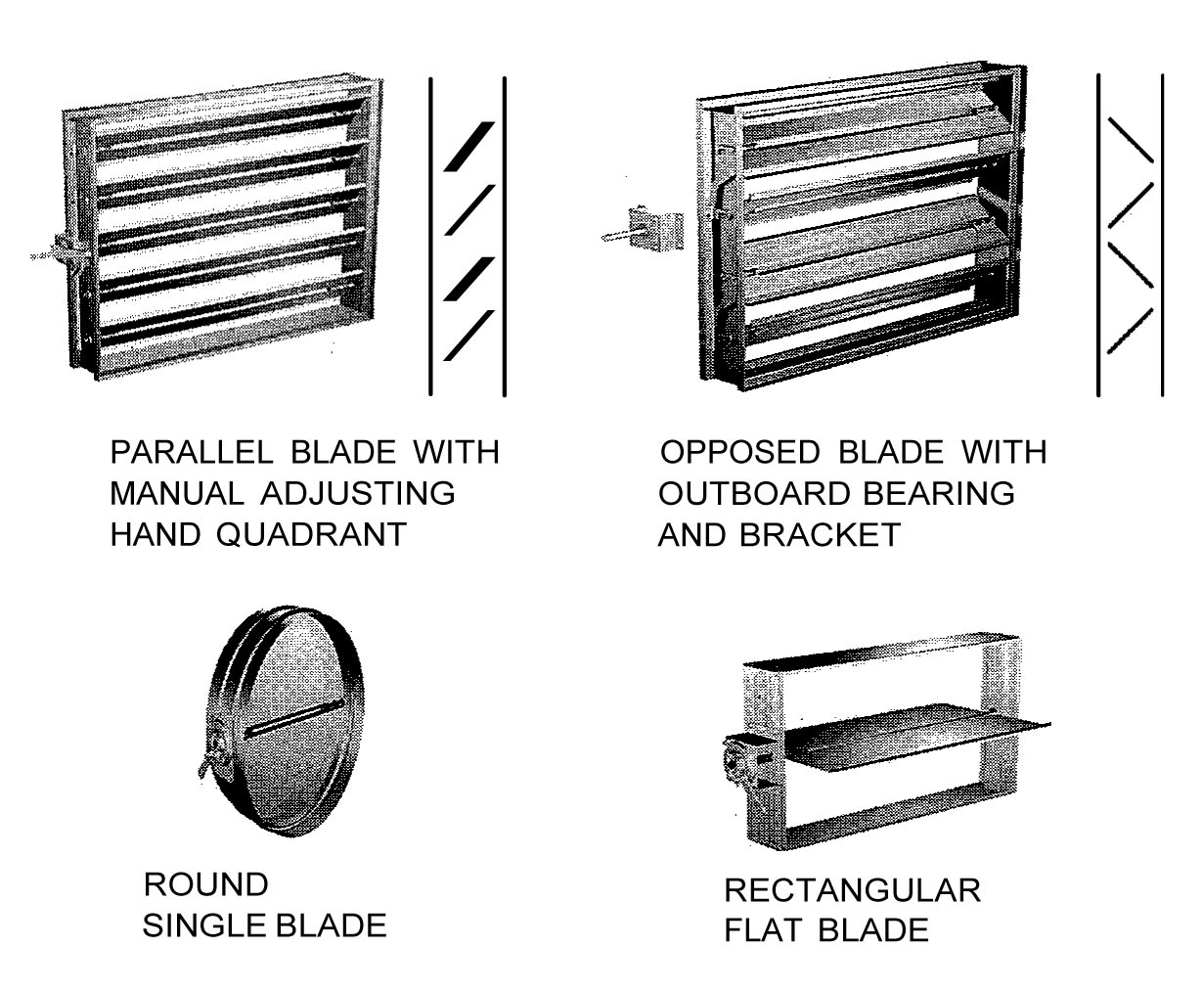
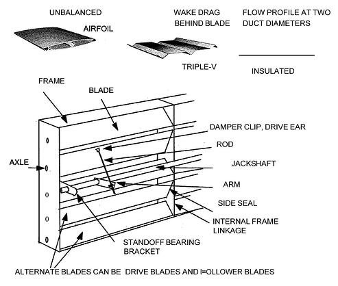
Figure above shows the two basic types of control dampers: parallel blade (PB) and opposed blade (OB). Sometimes, PB dampers are called single acting and OB dampers are called double acting in reference to the linkages. "The linkages from blade to blade can be located on the blades themselves but are more commonly located on one side within the frame. (Refer to the damper manufacturers' product reference manuals for construction details.) Figures below show the various details of dampers that affect flow and pressure losses.
In some dampers, not all the blades are the same height. A 24 in. (600 mm) high damper has slightly different size blades than one that is 22 in. (560 mm). Usually, one blade is larger than the others. On most blades, the damper shaft is mounted in the middle. Some are unbalanced, with the shaft located at about two-thirds position or at the end. Differences in flow characteristics result from these blade differences.
Blade seals can extend beyond the blade and affect the flow, particularly during the initial15° of opening. Different methods of sealing cause differences in flow characteristics. High-quality dampers have better linkages, and repeatability is easier to obtain. The Air Movement and Control Association International (AMCA) certifies airflow pressure loss testing.
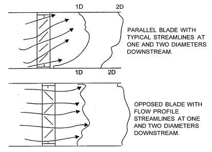
Motors, linkages, and jackshafts that block a damper opening affect flow. Many installation practices affect the predicted response of a damper. Figure above shows the difference in flow profiles coming off PB and OB dampers. PB dampers cause air to tum direction during most of their rotation. Airstreams tend to reconnect easily after separation by the blades. The pressure drop through the wide-open damper is a function of free-area ratio. The pressure drop as the blades modulate is more a function of the turning during the first 60° of blade rotation.
OB dampers change the free area quickly during rotation, and turning only occurs at blades not opposed by another airstream. A vena contract forms between opposing blades, and turbulence is high.
There is little experimental data available about the details of airflow around and inside dampers. Thick-walled orifices and airstream obstruction data are the main sources of theoretical data. Testing data from manufacturers is the main source of hard data. Since testing is so expensive, and purchases tend to go to the lowest-cost vendor, most manufacturers provide only basic information in their data sheets, and the effects of various irregular flow profiles have yet to be studied.
This article is based on an excerpt from the American Society of Heating, Refrigerating and Air-Conditioning Engineers, Inc. book “Dampers and Airflow Control” by Laurence G. Felker and Travis L. Felker.