The pressure loss through any damper is a function of the entering flow profile, the free area ratio, F, of the open damper area to that of the damper frame or wall area, the geometry of the damper installation, and the exit conditions as air leaves the damper. The most complete testing of dampers was performed for ASHRAE’s Research Project 1157. A complete analysis of the results is available in the book Dampers and Airflow Control published by ASHRAE Special Publications. Not only the full open losses, but also the modulating characteristics of dampers are experimentally defined.
The method for getting accurate prediction of damper pressure loss is too extensive to repeat here, but using several Tables found in the book, very accurate results can be obtained.
In general, DP = Co Pv , that is the pressure drop is equal to a loss coefficient times the velocity pressure.
The trick is obtaining the right Co based on the other conditions by applying engineering judgment.
Co = Fg x f(F2) where Fg is a factor based on flow profile and F is the free area ratio. The function depends on the AMCA[1] defined geometry.
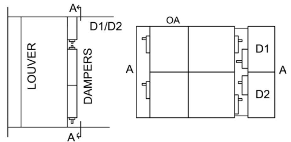
Below a typical drawing from the Damper and Airflow Control book is reproduced.
 Engineered Damper Assembly
Dampers and Airflow Control, Laurence G. Felker and Travis L. Felker, ISBN 978-1-933742-53-3 ©2009 American Society of Heating, Refrigerating and Air-Conditioning Engineers, Inc., 1791 Tullie Circle, NE, Atlanta, GA 30329 www.ashrae.org
[1] AMCA Air Movement and Control Association, 30 West University Drive, Arlington Heights, IL 60004 www.amca.org