Pressure Independent Valves (PI valves) are becoming more prevalent in buildings. Designers predict that by 2015 this technology will be standard in most chilled water applications, and will grow in hot water systems. The biggest benefit of PI valves, and the reason of their fast growth in the marketplace, is energy and installation savings. PI valves perform a continual balancing function at all times. This continual balancing optimizes the use of the water pumps and maximizes chillers performance by reducing the negative effects of low delta T. The PI Valves provide a constant flow regardless of the pressure variations on the system there is no need to install an additional balancing valve, this not only saves on material installation but also on balancing and verification costs. The lack of a balancing valve creates some challenges for the TAB technician. These challenges can be overcome by understanding how PI valves work.
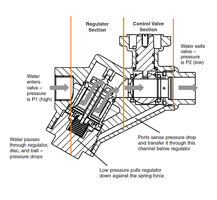
There are two types of PI valves, mechanic and electronic. Mechanical valves use a spring-diaphragm pressure regulator and the electronic valves use a flow meter in conjunction with a smart actuator. The mechanical PI valves diaphragm and spring combination reacts to any changes in pressure and positions a water regulator to restrict the flow of water to guarantee that an increase in pressure will not increase the flow of flow. The regulator also maintains differential pressure and is held constant across the valve. The electronic PI valves directly sense the flow of water and reposition the valve to always maintain the desired water flow.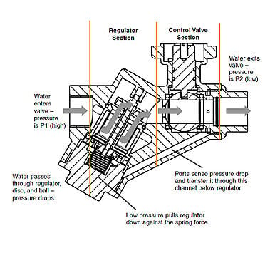
Electronic and mechanical PI valves always require a minimum differential pressure to operate; normally the minimum differential pressure is 5 psi. On the mechanical types the minimum DP is required to load the spring and diaphragm. On the electronic types the minimum DP guarantees the minimum water flow required by the sensor. If the valves are working below the minimum DP the pressure regulator mechanism is inoperable, and the valve will behave as pressure dependant, in this case the flow readings are not accurate. There is also a maximum differential pressure, normally of 50 psi. If this value is exceeded, on the mechanical valves there will be an extra stress to the diaphragm which can harm the regulator. With the electronic valves this causes the flow reading to be out of range; providing an inaccurate control.
When verifying a system with PI valves one of the first tasks of the TAB technician is to verify that the PI valves are operating between the differential pressure range. If the valves are working below the required minimum DP the flow readings become unstable. Some reports about PI valves not controlling properly are caused by this low DP. The most common cause of low DP is low pump speed. This is more noticeable on the valves furthest away from the pump. Another reason can include air on the system or fully open bypass valves. Once the minimum DP is obtained in all the valves, there is no need to modify the pump speed. All the valves will provide the rated flow regardless of the pressure in the system. TAB technician can focus only on verifying the flow on the valves and not worry about tweaking the valve and pump speed. This is the biggest benefit of a pressure independent system.
In a pressure dependant system, the typical arrangement consists of a balancing valve in series with a pressure dependant control valve (globe valve, characterized control valve, zone valve, etc). Normally the balancing valves have a calibrated orifice or venturi that allows the TAB technician to measure differential pressure and obtain flow. The flow is obtained either by calculating the DP and the device’s Cv, or by using flow/DP tables provided by the manufacturer. In a system with PI valves this option is no longer available. Flow needs to be verified using other methods.
There are three indirect methods of verifying flow at the unit level, air delta T, water delta T and coil pressure drop. The delta temperature method, the Air Handling Unit needs to be working under supply air and entering water design conditions. The design conditions will need to be verified and be based on the project documents. It is very important to verify the entering water temperature, supply air temperature and supply air flow rate are stable before taking any measurement, this guarantees its accuracy. Once the design conditions are verified, and if using the water delta T method, the leaving water temperature is measured. This reading should correspond to the design value, if not; the valve flow should be adjusted. The proper flow is achieved when the design leaving water temperature is measured. The air delta T method uses the same procedure but the flow is verified by measuring the discharge air temperature.
The coil pressure drop method consists of measuring differential pressure or pressure drop across the coil, but in this case there is no need to verify air and water design conditions. It is similar to the venturi method but uses the coil as a calibrated device> The flow is calculated using the pressure drop vs. flow curves provided by the coil manufacturer. This method is preferred over the delta temperature, it is practical and the most accurate. This is why the PI valves and coil manufacturers recommend the installation of PT ports on each side of the coil, ports 1 and 2 on the following graphic, to allow easier commissioning and verification.
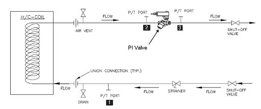 It is also recommended to install a third PT port at the outlet of the PI valve (port 3 on the graphic). The purpose of this port is to verify the valve and ensure that it is working under the recommended differential pressure range.
Some PI valves are built with integrated PT ports; these ports will have the same function as ports 2 and 3 on the graphic. Their only purpose is to verify the valve operation and not flow. Compared to a calibrated orifice or a venturi that has defined geometries designed specifically for the purpose of obtaining accurate pressure readings, a PI valve body is not suitable to perform flow calculations using pressure drop. The reason is the complex geometry of the valve with multiple moving parts, including the regulator. The regulator moves when there is change in pressure, plus turbulences inside the valve body making the measurements change constantly. The results are inaccurate measurements that are out of the accepted tolerances. The misconception of using the integrated PT ports to obtain flow; has lead to some frustration in the field. Because of this, manufacturers have decided not include PT ports on their PI valves to avoid any confusion. Recommendations installation of external PT ports instead as stated in the graphic.
Before using any of these methods the TAB technician should be familiar with the NEBB and/or TABB recommended water balancing procedures.
A technology that is becoming very popular is ultrasonic flow meters. The price has decreased considerably; these sensors offer the best results in measuring water flow and do not require any calculation. They are the easiest to use, and provide the fastest set-up per unit. The labor savings due to easier setup and reliability pays for the investment in a very short period of time.
Industry has seen similar changes on the air side when VAV air systems became more sophisticated with pressure independent VAV boxes that use air flow sensors. Today balancing a pressure independent VAV air system requires some advanced technology that relies heavily on electronic instruments. Even though the technology is advanced it doesn’t mean that it is complicated or expensive. Today, electronic air balancing devices are the standard in the industry. The evolution of these instruments has led to the adoption of even more advanced electronic devices. Some even use computers to display and process as well as collected data information. With the development of specialized control components on the water verification devices development will follow a similar trend to the air instruments.
As with any new technology time is necessary to learn that PI valves are not the exception, but once the operation is understood it is very easy to realize the benefits of PI valves. These benefits are more significant to the TAB technician for easier verification and time savings compared to balancing regular pressure dependant valves.
Watch this one minute video on how a pressure independent characterized control valves operates. For additional technical support call 877-833-1609.