Q&A on Testing, Adjusting and Balancing, Belimo's Pressure Independent Valves
Over the last decade, Pressure Independent (PI) valves have become somewhat commonplace since they are ideally suited for today’s variable speed pumping systems. PI valves are designed to deliver a specific flow to a coil for each value of the control signal - regardless of pressure fluctuations that occur in a typical system. Testing, Adjusting, and Balancing (TAB) agencies, the Engineer of Record, and valve manufacturers work together to assure project documents incorporate PI valve “best practice” specifications for TAB flow validation.
The following questions and answers address common TAB issues experienced when encountering PI valves on a project.
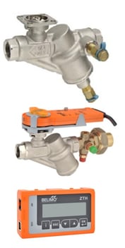
1. How do TAB professionals verify flow with a Belimo PI valve? Belimo offers multiple ways to verify flow:
1. Pressure Independent Characterized Control Valves (PICCV) with integrated pressure temperature (PT) ports or external PT ports use four methods for flow verification and commissioning System Verification –
Total System Flow Method
Terminal Level Verification – Air Delta T Method
Terminal Level Verification – Water Delta T Method
Terminal Level Verification – Coil dP (Delta P) Method
2. PICCV’s furnished flow verification orifice and actuator model LRB24- SA or KRB24-3 require positioning the flow clip for maximum flow and then verifying the setting with manometer reading; measured in inches of water across the PT ports. Reference the flow chart found in PICCV Technical Documentation to verify flow settings.
3. Electronic Pressure Independent Valve (ePIV) or Belimo Energy Valve™ flow verification is read or adjusted with the ZTH handheld tool. Flow data from the ePIV can also be accessed with PC-Tool computer software. Flow data from the Energy Valve can also be accessed by using a web browser and logging to Webview. Flow readings are sourced from an integrated in-line ultrasonic or magnet flow meter and are also used by the actuator logic to deliver pressure independent flow to the coil.
2. When the TAB professional is validating maximum coil flow is the valve required to be wide open?
PI  valves may not be required to be wide open to achieve full flow.
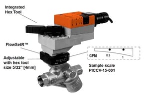
With mechanical PI valves, travel adjustment is used to achieve full flow when coil design flow is less than the capacity of a wide-open valve. Travel adjustment of the PICCV with Multi-Function Technology (MFT) proportional control actuator (2-10 VDC) is programmed in the factory, or in the field with the ZTH handheld tool. Travel adjustment of 3-point floating actuators is set by adjusting the mechanical travel limit to match the GPM of the FlowSetR™ scale.
Travel adjustment is not necessary with ePIV or the Energy Valve because the available differential pressure across the control valve is used to achieve the flow setting. The flow feedback signal is used by the actuator logic to throttle the valve to the position needed to obtain the programmed flow setting - just like pressure independent VAV box actuator behavior.
3. What is the position of the override handle if the mechanical PI valve is “travel limited” to achieve full flow? The override handle will stop at the travel limit the actuator was set for after it was commanded to achieve full flow. PICCV actuator travel limit is between 38 and 90 degrees rotation depending on the valve model and design flow requirements. For PICCV’s refer to the online calculator to determine field settings. To view PICCV factory flow settings and associated travel angle refer to the running timetable.
4. Does the TAB professional need to adjust the travel setting of the mechanical PI valve? Yes, if the PI valve is not factory set to a flow limit then the travel setting needs to be adjusted.
If the Engineer of Record has approved the PI valves with factory set flow limits then the flow data tag value should be verified and field adjustment is typically not required. If the TAB professional is directed to fieldset coil flow to match design flow to ± 10% tolerance utilize adjustment methods detailed in Answer 1 above. Consult the project specifications for TAB clarification.
TAB guidance language examples from Associated Air Balance Council (AABC) and National Environmental Balancing Bureau (NEBB) are detailed below. The AABC specification and NEBB standard do not direct the TAB professional to change factory set flow settings furnished by the PI valve supplier. The NEBB standard states the flow rating from the data tag is the verification target.
REFERENCE: AABC specifications found in Section 230593 – Testing, Adjusting and Balancing for HVAC, subsection 3.8.D, for systems with pressure-independent valves at the terminal: “(1) first measure differential pressure across the valve to verify that it is within manufacturer’s specified range and then (2) perform temperature tests after all flows have been verified”..
REFERENCE: NEBB Standards Section-9, Hydronic System TAB Procedures, subsection 9.3.3, Calibrated Balancing Valves, Self-Adjusting Valves (i.e. PI Valves) states: “The NEBB certified TAB Firm shall verify the valve flow rating from the data tag, and verify by differential pressure measurements, if available, that the pressure drop across the valve is within the control range of the valve”.
RECOMMENDATION: Most coil schedules today are generated from computer calculations and the design flow value can be displayed to a hundredth of a GPM. Belimo factory set flow offerings for PI valves represent typical coil flows and may not exactly match the calculated flow. Belimo advises the Engineer of Record to adjust the coil schedule to match the flow setting of the valve before contract documents are published. For example, if coil design flow is calculated to be 0.7 GPM and the valve schedule was approved with a factory set flow of 1.0 GPM; the contract document’s design flow should have been adjusted from 0.7 GPM to 1.0 GPM. If not, the installed valve will have a maximum flow of 0.3 GPM higher than the design. The maximum flow is now 42% higher than the design which is beyond the standard ± 10% tolerance TAB professionals typically seek to verify.
Modifying the coil schedule from 0.7 GPM to 1.0 GPM will positively impact the TAB professional’s ability to achieve their goals and will not impact operational performance of the coil. Most of the time the coil is operated at part load and there is no impact. When the coil is operated at full load the temperature control system will become satisfied with 0.7 GPM delivered to the space when the coil inlet water temperature is at design temperature.
5. What is the impact on total system flow if the PI valve is factory set to a maximum flow that is different than the design flow in the contract documents?
A5: The impact will vary based on the aggregate deviation of factory set flow vs. design flow. If the contract documents detail the coil design flow to be 0.7 GPM and the installed PI valve with factory setting was approved to be 1.0 GPM the impact is only 0.3 GPM. For a single valve, or a few valves, this is negligible. However, if this scenario is hypothetically multiplied by 100 for a large project the deviation is 30 GPM which may be noticeable. To resolve this Belimo advises the Engineer of Record to adjust the coil schedule to match the flow setting of the valve before TAB work commences.
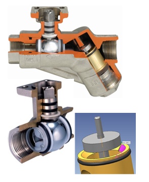
6. Are Belimo PI valves prone to clogging with dirt or debris? No, Belimo PI valves utilize Characterized Control Valve (CCV) technology where the ball and seat arrangement is “self-cleaning” and resistant to clogging; unlike some mechanical PI valves that utilize short-stroke globe valve trim. Clogged PI valves are very rare but if the installation contained excessive dirt and debris upon start-up hydronic components can become clogged.
The PICCV also utilizes a differential pressure regulator that passes normal debris present in the hydronic loop. When the valve begins to open, water flows first through the wide open “upper section” of the regulator. Debris smaller than 9/64“ (3.55mm) passes through the regulator then it exits the valve. After flow is established the regulator moves in response to pressure changes to maintain the flow setting. When the valve closes the regulator returns to its wide open position.
The ePIV and Energy Valve are even more resistant to clogging due to the absence of a differential pressure regulator.
7. Should strainers be used for each PI valve? Maintain standard design practices concerning strainers; Belimo PI valves do not require strainers.
8. Do PI valves require more system pump head to achieve full flow than standard pressure dependent valves? No, Belimo PI valves require 5 psid to achieve full flow which is equivalent to a standard pressure dependent valve sized to a 4 psi pressure drop in series with a circuit setter that typically induces a pressure drop of 1 psi or greater.
The ePIV and Energy Valve use the available differential pressure across the valve and the actuator throttles to any position needed to obtain the flow setting - just like pressure independent VAV box actuator behavior. Under light load conditions flow settings can be achieved with as little as 1 psid across the valve.
9. Do PI valves save energy over the life of a building? Yes, Belimo has successfully documented this in the following case studies including: Shell Point Retirement Community in Fort Myers, FL, the corporate headquarters of The Phoenix Companies, Inc. in Hartford CT, and the Eglin Air Force Base near Pensacola Florida.
PI valves are dynamically balanced delivering the proper flow to the coil over any operating load condition. Overflow and underflow are eliminated providing better comfort and efficient system performance. For further information on PICCV performance refer to straight answers to your questions about PICCV's and the PICCV brochure .
Learn more about the ePIV or Energy Valve and their integrated ultrasonic or magnetic flow meter by viewing the ePIV product brochure and Energy Valve product brochure found online at www.belimo.us.

