Factors to Consider for Actuation on Large Multi-Section Dampers
When designing commercial HVAC damper applications, many factors are considered that impact actuator selection. Every actuator manufacturer has an applied torque limit to consider. When factoring in the controllability of a damper, the control system is simply sending a control signal to “an actuator” to drive “a damper.” The control signal is not affected that multiple damper sections or multiple actuators must operate as “one” device. Damper manufacturers also have specific product considerations such as rough opening with dampers, manage shipping size limits, damper assembly configurations, and damper performance. Application, product, and manufacture terminology vary when discussing large dampers or high torque applications.
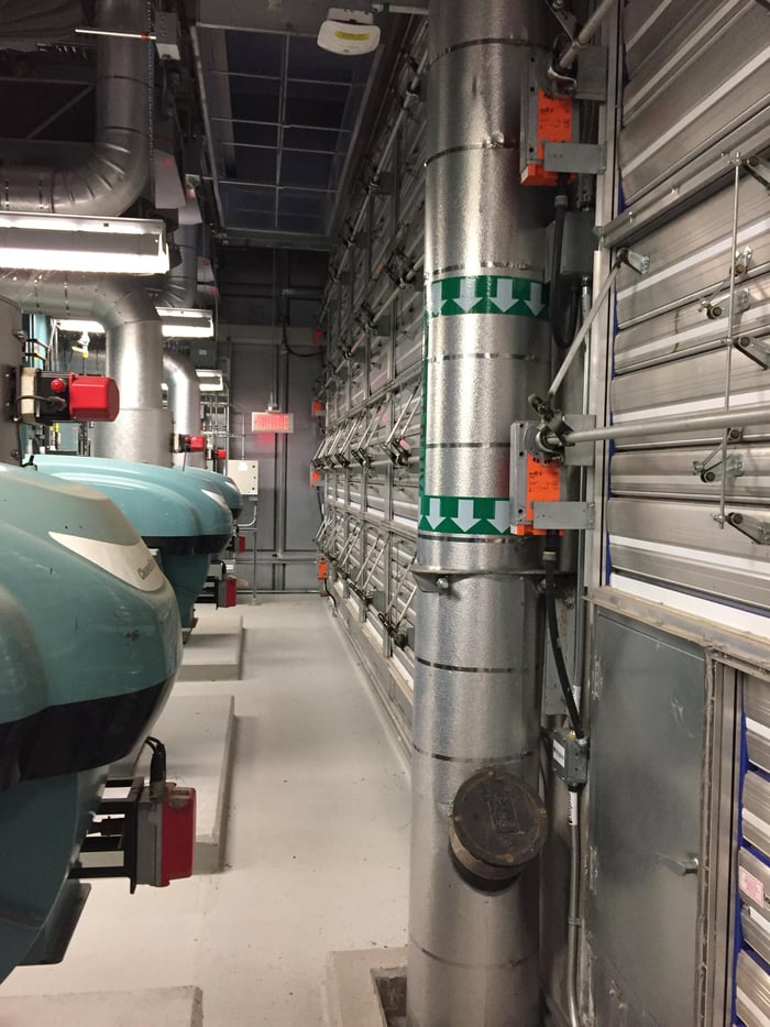
Installation recommendations often do not default to use the largest torque actuator possible. They may recommend multiple ‘smaller’ actuators mounted and wired to deliver high torque efficiently to damper shafts to optimize torque performance of torsional load and elasticity. However, this also has limits. If a damper requires 300 in-lb of torque, a recommendation would be one 180 in-lb actuator on the left and one 180 in-lb actuator on the right. Rather than one 360 in-lb actuator installed on one side—the application benefits by applying the actuator torque effectively to reduce the torsional load. A long and wide damper assembly may have a jackshaft assembly for interconnecting the damper sections. Torque applied to a long jackshaft from one side can twist the shaft. Splitting the actuator torque across the damper dramatically improves the performance of the dampers. For example, when an actuator drives a long damper shaft from one side, it may twist when delivering the torque. Too much twist will reduce the farthest dampers’ angle of rotation and ultimately affect the air volume or increase the pressure drop across the damper.
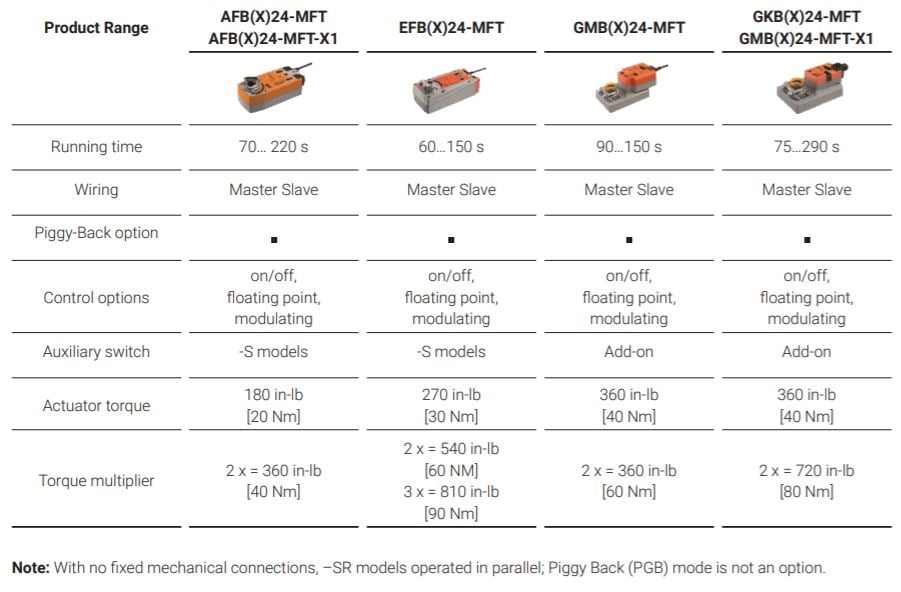
Piggy-Back mode (PGB) is the functionality that enables actuators to work together to increase the delivered torque. Piggy-Back (PGB) is used when coupling two or more actuators on one or multiple mechanically linked shafts to provide higher torque for an application. Piggy-Back (PGB) operation is typically available with the highest torque Multi-Function Technology (MFT) actuators and the AF, EF, GK, GM.. series with MFT.
Products with Piggy-Back Mode
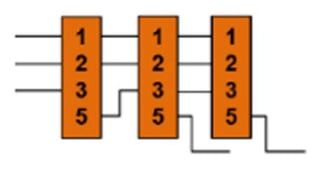
The PGB mode activates automatically with actuator wiring for Master Slave control applications. The wiring defines which actuator is the Master. The Master actuator is responsible for the control and performance of the mechanically coupled Slave actuators. Piggy-Back Multi-Function Technology actuators provide the correct amount of actuator torque equal to the application’s required torque. The basis for Piggy-Back control requires a mechanical and rigid interconnection.
 The preferred wiring method of Piggy-Back applications is Master Slave. The Master actuator receives the control signal from the controller. Every Slave actuator connected to the Master (U5) receives operational commands from the Master. For position feedback, select one Slaves’ feedback signal back to the controller (if applicable). If the Master fails, the Slaves will not respond to the control signal. Belimo Multi-Function Technology (MFT) actuators offer the ability to configure functions to match application needs. The ability to configure control and feedback signal, runtime, and adaption of the angle of rotation.
The MFT platform increases a contractor’s field flexibility with one configurable product. With the PC-Tool and or ZTH, the field technician can easily configure specific actuator functionality. Additionally, all MFT-based products incorporate Belimo MP-Bus communications. MP-Bus is a digital communication field bus that works over a three-wire low voltage circuit. When activated, Piggy-Back mode uses MP-Bus to control mechanically connected actuators (Slaves).


