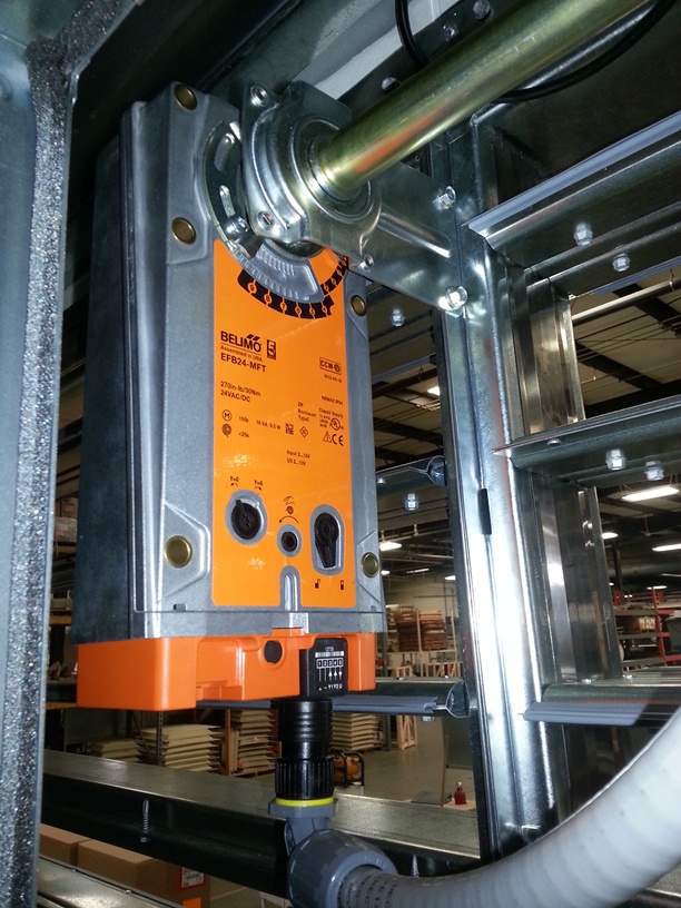
Importance of Dampers and Actuators in HVAC Systems
Dampers are the final control devices for almost all airflow in HVAC systems. Actuators are the interface between the control system and the mechanical system and are critical to accurate control.
Typically, 80% or more of direct digital control (DDC) outputs in the HVAC portion of the system go to actuators. If they are not positioned accurately, then all other portions of the air system suffer. Too often, the torque necessary to move a damper is the only selection criterion; accuracy is not an important issue. A controller cannot compensate for incorrect damper or actuator sizing. The TAB contractor or commissioning authority can only some times set airflows to correct for problems.
Concentration on the final control elements in the design process can solve most of these problems. Equipment sizing is very rarely a problem. The airflow system delivering most of the conditioned air to the occupants causes the difficulties. Factory-built mixing boxes control flow with difficulty due to space constraints. The willingness of design engineers to design around some space constraints leads to systems that work only part time.
As the size of a project grows, there is more complexity and more chance for small miscalculations to become a major problem. New design ideas present a greater chance of problems. Shown below are some of the following sources of airflows that affect space conditions:
- Wind effect on intakes and exits (overflow and underflow occur periodically) Damper leakage
- Duct leakage-both return and supply
- Infiltration
- Exfiltration
- Cross flows from air handlers or multiple-tenant equipment
- Doors-both between internal spaces and to the outside
- Elevator shafts
- Exhaust fans
- Plenum vs. ducted returns
- Relief-exhaust vs. return-air fans
- Ventilation air quality
- Heat-recovery equipment
- Flows in voids and hidden spaces
- Fans
- Stack effect and space or zone static
- Ventilation effectiveness (fresh air must be distributed well)
- Cross contamination of exhaust and intake (potentially a major problem)
- Variable-air-volume (VAV) box flow variation (typically, while the supply varies by location, the returns do not vary; this can result in irregular flow patterns)
- Leakage paths through ceilings and floors
- Leakage paths through pipes, chases, shafts, and any penetrations
- Unknown variables and factors [1]

Figure above illustrates airflow paths in a typical system.
Learn more from this publication: Dampers and Airflow Control which can be purchased at ASHRAE online.
[1] ISBN 978-1-933742-53-3 ©2009 American Society of Heating, Refrigerating and Air-Conditioning Engineers, Inc., 1791 Tullie Circle, NE, Atlanta, GA 30329 www.ashrae.org

