This document details the flow verification and commissioning procedures in HVAC plants, water distribution can be accomplished at constant or variable flow. Each type of distribution system has advantages and disadvantages. Today variable flow systems using electronic 2-way control valves became generally accepted as the industry standard due to their benefits. The main reason for becoming the industry standard is reduced pumping cost, which is a result of pump head and flow. Meaning, the more control valves are closing, the lower the total flow. Another reason is that the plant can be designed with a diversity factor because flow is only needed where energy is demanded. Besides these advantages, there are disadvantages in today’s variable flow systems.
Disadvantages of Today’s Systems:
Time consuming balancing effort
According to its flow design each control valve requires a balancing valve to adjust the hydronic circuit. The balancing procedure dictates the quality of the system and requires highly skilled technicians and tools. During the balancing all control valves must be in their open position. However, as soon as the system is running, depending on different cooling or heating load requirements in the building, valves are permanently closing and opening which results in a dynamic system pressure. Balancing variable flow systems is time consuming and can be conducted only under “static” design conditions.
Rebalancing required when adding to system or remodeling
In a conventional system, if terminals are added the whole system needs to be rebalanced because some existing terminals must be throttled back. Or imagine a 10-story-building where every 2 months one floor is being remodeled in which balancing of the whole system is required after finishing each floor. Of course this applies also to buildings with changing tenants or new utilization of spaces.
Poor valve authority at average or low load
Only 1% of the time is a building typically running under design conditions. The other 99% the hydronic system needs to provide an average load of 50%. Thus flow is reduced to 20% and differential pressures across control valves increase. Since the Cv rating of the valve was sized for design conditions, the valve authority decreases and the modulating valve is downgraded to one acting open or close only. The result is anticipated hunting.
Potential spreading of control problems
Control circuits are interactive. Therefore when one control valve closes, the differential pressure on other circuits increase and the associated control valves must close to compensate. So when one or more loops are instable, control problems can spread to other control valves.
Low DT reduces efficiency
If flow is higher than required, DT will decrease and result in a cooling plant with lower return temperatures to the chiller and reduce the efficiency. If a chiller cannot run at peak efficiency, it is more likely that the next chiller in a series will be forced to start sooner than required causing additional electricity and maintenance costs.
The opposite happens in a condensing boiler, where a higher return temperature can avoid the condensing process when the dew point of the exhaust gases cannot be achieved.
The same phenomenon can happen in coils. In a heating coil for instance, overflow will result in a lower DT and decrease the coil’s performance which can result in discomfort due to a low room temperature.
The Revolutionary Solution:
With the PICCV all the disadvantages of variable flow systems are eliminated to represent the best hydronic solution for most HVAC-applications. The Pressure Independent Characterized Control Valve, PICCV, is based on the proven Characterized Control Valve, CCV, technology. In many tests and surveys, the CCV has outperformed globe valves due to a true equal-percentage valve characteristic and higher close-off ratings.
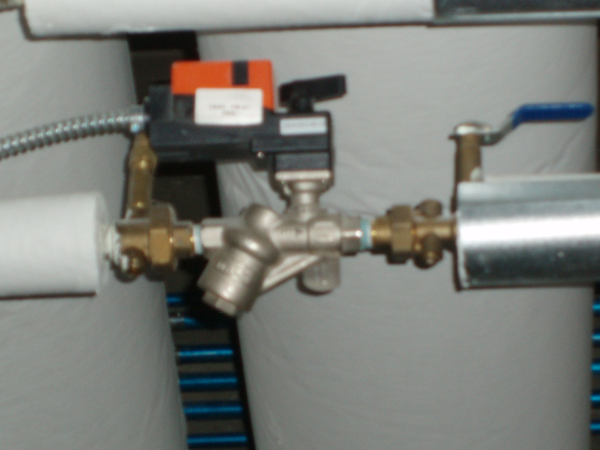
In a PICCV the CCV is combined with a differential pressure regulator. This regulator maintains a constant flow passing through the valve regardless of pressure variations in the system. The flow is held constant, but independent on the degree of ball opening. This is the most important at part-load; for instance when a PICCV with a nominal flow of 10 GPM operates at 3 GPM, a flow of 3 GPM is maintained.
The PICCV is available in the flow range from 0.5 to 100 GPM (1/2” to 2”) and a pressure operating range from 5 to 50 PSI.