Demystifying the Manual Balance Valve
Published by
Aaron Nobel
on
When it comes to the topic of components in a hydronic piping package, the Manual Balance Valve (MBV) is a common source of confusion in the selection and flow verification. In a piping package, MBVs are used in conjunction with pressure dependent valves, usually assembled directly to the valve outlet in the standard return side of the coil application. This article aims to provide some practical information to enhance your understanding of these essential components and the selection and commissioning methods.
Balance valves serve an essential role in the efficient operation of a hydronic system by balancing of hot or chilled water to terminal units to design flow rates. In an unbalanced system, water will flow through the path of least resistance resulting in terminal units nearest the pump experiencing excess flow. In contrast units farthest away from the pump are likely to have insufficient flow. These systems create noise issues at units with excess flow; individual coils suffer from incorrect flow and inefficient heat transfer, temperature variation throughout the building leading to occupant discomfort, and wasted energy. Conversely, well-balanced systems benefit by facilitating a comfortable indoor climate, optimal flow distribution throughout the system, energy savings, trouble-free operation, and ease of maintenance.
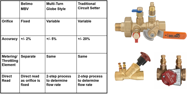
Manual Balance valves are divided into two main types: fixed orifice and adjustable orifice. The advantage of a fixed-orifice Venturi balance valve is that the metering and throttling elements are separate, allowing for a single-step process to determine the flow rate. The Belimo MBV combines the functions of an isolation valve, union, manual air vent, and two pressure temperature read-out ports with a high signal/low loss Venturi, which allows for easy commissioning.
The selection of the Manual Balance Valve is based on the coil flow requirements. The MBV flow range should be taken into consideration, optimally selecting a valve with the requirement as close to the middle of the range rather than the upper or lowest extremes. Most metering devices used by balancing professionals register up to 100 inches of the water column. The recommended operable flow range should consider the MBV capacity at 10” through 90” wc. Belimo conveniently publishes this information in the product catalog as well as datasheet specifications. Using Select-Pro software for your piping package selection will also consider the valve capacity (Cv) and fluid velocity assuring efficient, silent operation.
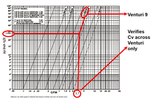
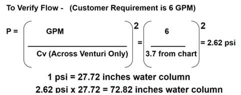
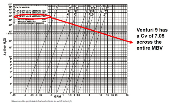
During the commissioning and balancing of a system, the balancing professional will use a device to read the pressure differential (Dp) across the Venturi and reference the valve’s flow chart to determine the flow. The flow chart is based on the Venturi Cv, which can be used to determine the precise Dp requirement for the desired flow rate.
Let’s take an example of a flow requirement of 6 GPM using a manual balance valve with a #9 Venturi. Following the flow chart to the 1 PSI line will yield the Venturi Cv.
Additionally, the flow chart will often provide the Cv across the entire MBV for determining pump requirements.

A few simple concepts are all it takes to successfully select and commission Manual Balance Valves, which are essential to a properly balanced and efficiently operated hydronic system. Additional resources are available online, along with a link for Select-Pro.

