Corridors are typically a means of egress during fires or emergency events. During normal operation they require ventilation. In some code jurisdictions or building design requirements, pressurization or smoke extraction is also required.
This article presents several means to provide pressurization or smoke extraction with ventilation and details the operation of the controls, dampers, and actuators.
The operation of corridor smoke exhaust influences and is influenced by the other smoke control tactics in a fire and the fire protection and mechanical engineers model the airflows with respect to one another. Figure 1 shows a larger picture than just the corridors.
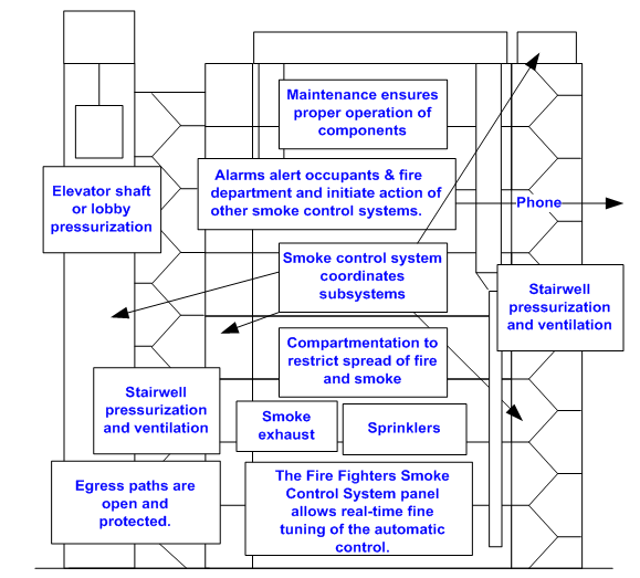 Fiqure 1: Some of the strategic elements in fire and smoke control.
Background
The model codes used in the United States and some other countries – International Building Code ((IBC 2012) and the International Fire Code (IFC 2012) along with the International Mechanical Code (IMC 2012) have various requirements for corridors in commercial buildings. The walls must be constructed as smoke partitions and in some cases as fire partitions. Minimum widths are established. Mechanical ventilation, travel distances, and other requirements are also covered. Chapter 4 of the IBC establishes requirements based on occupancy type. Chapter 7 details the requirements with respect to structure. Chapter 9 details the active or engineered system
All smoke control equipment status must be indicated on the fire-fighter’s smoke control system (FSCS) panel. This includes smoke control dampers (IFC 909.16.1). Control of all smoke control equipment must be possible from the FSCS (IFC 909.16.2) with the exception of complex systems where other provisions are allowed.
Smoke Extraction
In corridors there are jurisdictions and individual projects where corridor damper and fan systems are required to clear the corridor of smoke and prevent spread to adjacent floors. Since ventilation is also required, the two functions must be coordinated. This can be achieved with dedicated or common (non-dedicated) equipment.
Either a “sandwich” or “building” pressurization type of approach is usually used. See Figure 2.
In a sandwich pressurization system –
a) The corridors on the fire floor are negative with the fan pulling smoke out of the floor. (Supply closed, return or exhaust open fully.)
b) The floors above and below the fire floor are pressurized more than other floors. (Supply fully open, exhaust off or closed.)
c) The corridors on other floors of the building operate normally. (Typically partially open supplies and exhausts.)
In a building pressurization system approach –
a) The corridors on the fire floor are negative with the fan pulling smoke out of the floor.
b) All other floors operate normally. They are under a positive pressure with ventilation air. Since the fire floor is very negative, the difference in pressure is large enough to prevent smoke spread to the non-fire floors.
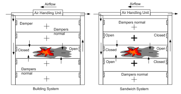
Figure 2: “Building” vs. “sandwich” pressurization system.
Figure 2, shows the overall concept of a non-dedicated system – the ducts move ventilation air under normal circumstances and are used for smoke control only in an emergency. However, variations are common in corridor systems as there are a number of ways to achieve the goals. Among the possible methods are:
a) Two rooftop fans (supply and exhaust) and separate ducts to the corridors.
b) One reversible fan that delivers ventilation air in normal operation and exhausts air during an event. In this case there are other provisions for make-up air, reliefs or local exhausts. Various factors influence the approach that is best. All pressures – positive or negative – due to stack effect; lobbies, elevators, or natural ventilation, or attached rooms and spaces are considered.
c) If there is sufficient make-up air elsewhere, an exhaust fan alone may be used to move air out of the corridor. No supply fan.
See Figures 3 and 4 for drawings of the two approaches. Figure 5 shows a vertical representation of a high-rise corridor duct system in a multistory building. The point is that the same duct feeds or draws from all of the dampers. The system must be balanced in order to provide the correct amount of ventilation air on each floor. When a fire event occurs, the air flow requirements change.
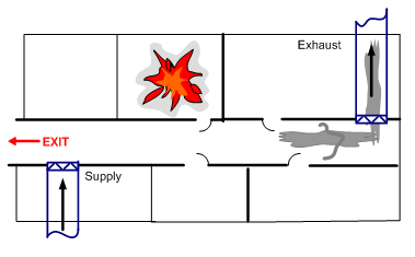
Figure 3: Separate supply and exhaust ducts in a corridor.
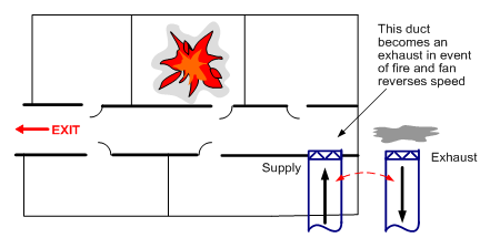
Figure 4: Single duct serves as supply and smoke exhaust in a corridor.
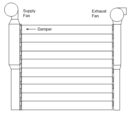
Figure 5: Fan and ducts in 10 story building.
The pressure at the discharge of the fan is higher than at the bottom of the building. However, the required quantity of air going through each damper is the same during normal operation.
The damper at the top of the building will be open much less than that at the bottom of the building. Even with careful calculations to use different sizes of dampers, balancing will be needed to get the correct flow through each damper. In addition to pressure losses in the duct and across the dampers, local exhausts and some stack effect will cause variations that cannot be precisely calculated. The goal will be to have the furthest damper full open to use the least fan energy while delivering the right amount of ventilation air on every floor.
Fans
The fan sequence for each of the cases above is straightforward. With the Figure 3 two duct system both the ventilation supply fan and exhaust fan are on when occupied (or optimizing or under control of an air quality sensor). If a fire alarm activates or smoke is detected during unoccupied periods, the fans are turned on again. This is the same for both sandwich and pressurization systems. At the same time the stairwell pressurization system is activated and alarms are issued. This is beyond the scope of this article.
If using the Figure 4 geometry, then the fan is on and supplying air during normal occupied times. In event of a fire, the fan goes to the reverse air flow direction – exhaust mode.
Dampers
Any individual damper in either type of system must perform several functions. These dampers can be parallel blade (PB) or opposed blade (OB). In most cases an OB will have more accurate resolution for setting minimum position and full open the flow is the same for either type.
The dampers must be UL 555S (UL 555S) listed as smoke dampers (IFC 909.10.4). In some cases the damper must also be a fire damper that meets UL 555 (UL 555) as well so combination fire and smoke dampers would be required. Most corridor walls must be fire rated. However, if the fire damper function could interfere with the smoke control system operation, then installation of a fire damper is not required (IBC 717.2.1).
The actuated damper operation will be similar for all cases. Here we will discuss the detailed operation for only the Figure 3 supply and return duct case in a sandwich pressurization system.
Normal operation. Both supply and exhaust dampers open to a minimum position. Balancing dampers in series with the smoke control dampers cannot be used. They would block some flow when the damper went to 100%.
In event of a fire:
Fire floor
a) Supply damper closes so that smoke is not pushed into other areas.
b) Exhaust damper opens 100% to remove smoke.
c) In some cases the dampers are also fire dampers and will close if temperature inside damper frame reaches 165°F. The FSCS panel has override switches to reopen the damper with a secondary sensor to again close damper if the temperature reaches 250°F. This is discussed below.
Floors immediately adjacent to fire floor
a) Supply damper opens 100% to pressurize and restrict smoke entry
b) Exhaust damper closes 100%
All other floors
a) Dampers remain in normal operation
b) Variations do exist
Belimo FSAF24-BAL Solution
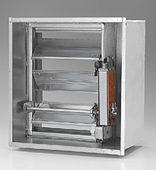
Figure 6 shows a corridor damper with the FSAF24-BAL. Several manufacturers produce similar products. Not shown is the front grill. The damper is installed in the corridor wall and the actuator provides the sequence needed for ventilation and smoke control. The actuator is three position – closed, adjustable mid-position, or open 100%. Figure 7 shows operation.
Figure 6: Ruskin FSD60-FA-BAL
With no power the actuator springs closed – unoccupied, fire present at damper, or smoke control stop air flow.
With 24V on wire 2, the actuator opens to the balancing position as set by the potentiometer on the face – this is the normal operation ventilation air position. Each actuator is set at a different potentiometer position as balancer measures flow.
When wire 3 receives 24V the actuator opens 100%. – full pressurization or smoke exhaust mode.
These are the positions needed for the corridor ventilation and smoke control.
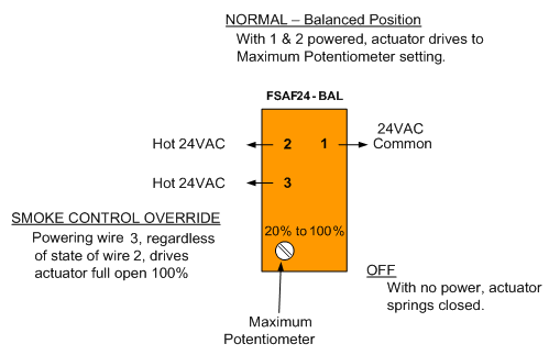
Figure 7: Detail of FSAF24-BAL.
Smoke control system program mapped to actuator function
The sequence detailed above under dampers can be mapped against the needed actuator operation and programmed into the smoke control system panel as shown below.
Normal operation: Wire 2 is powered, damper in ventilation position.
Fire floor
a) Supply damper: No power, damper closes.
b) Exhaust damper: Wire 3 powered to open damper 100%.
c) For fire dampers Wire 1, common, is always connected unless the primary sensor opens. See Figure 8 description.
Floor(s) immediately adjacent to fire floor
a) Supply damper: Wire 3 powered to open damper.
b) Exhaust damper: No power, damper closes.
All other floors
Dampers: Wire 2 is powered.
Figure 8, adds more detail to how the damper is controlled. (Note that there are other wiring variations not covered here. For example the secondary sensor could be between the Override relay and wire 3.) A smoke damper would have neither the 165°F high temperature primary sensor nor the 250°F secondary senor.
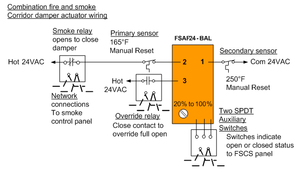
Figure 8: Control of FSAF24-BAL-S actuator.
In Figure 8 the smoke relay is normally closed and power is delivered to the actuator. The damper drives to the minimum position setting.
Combination fire and smoke dampers have two t”emperature sensors (“heat responsive devices” per UL555) – primary and secondary. If the temperature rises to 165°F (74°C) the primary opens and the damper springs closed. It does not go to the potentiometer position since it does not have power. If the Override relay is made by intervention from the FSCS panel then wire 3 is energized. This bypasses the primary sensor. The damper then opens to the 100% position instead of the ventilation position.
If the temperature at the damper again rises and reaches 250°F (121°C), then the secondary sensor opens and damper springs closed and stays closed until manually reset.
To summarize:
By powering wires 1 and 2 with 24V the actuator drives the damper to the required position for ventilation.
By cutting power the actuator springs the damper closed.
By powering wires 1and 3 the actuator drives the damper 100% open regardless whether wire 2 has power or not.
Figure 9, shows the Fire Fighters’ Smoke Control System panel with indication lights that are given status by the auxiliary switches on the actuator. Each fan and damper has its own status lights and override switch. The signals for light indication at the panel are carried via the network from actuator auxiliary switches, damper blade switches, magnetic contact switches, or programmable actuator signals.
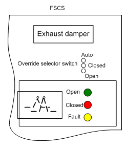
Figure 9: Portion of Fire Fighters’ Smoke Control Panel.
Proportional actuator with Minimum position control
Another way to achieve the same sequence is provided by use of a proportional 2-10V actuator and an SGA24 minimum position switch. This is a different actuator than the BAL shown above. It is a standard 2-10VDC control actuator.
The wiring schematic is shown in Figure 10. Figure 11 shows the minimum selector which can be used to set the mid-point balancing position of the actuator.
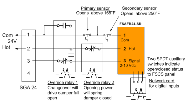
Figure 10: Proportional actuator controlled by minimum potentiometer.

Figure 11: Proportional minimum potentiometer
The sequence of operation of the wiring diagram in Figure 10 is as follows:
With no power on both Com and Hot, damper springs closed. This would be the typical unoccupied position. The “closed” auxiliary switch indicates the damper is closed and the network card transfers the position indication to the FSCS panel.
With power going to the SGA24 and actuator, the signal out of the SGA on 3 goes to the actuator input 3. (4 is not used in this sequence. It would allow modulating control of the damper in addition.) The 2-10 VDC signal positions the actuator and damper from zero to 90 degrees to be set by the balancing contractor.
If Override relay 1 makes 24V power is delivered to 3 of the actuator which causes it to drive full open. At the same time the 165°F sensor is bypassed. (The 250°F remains in the circuit as a final safety should fire be present too close to the wall.) This would open the damper fully if it is an exhaust on the fire floor or a supply on an adjacent floor.
If Override relay 2 makes, power is cut to 2 of the actuator and it springs closed. This would achieve needed closure of a supply on the fire floor or an exhaust on an adjacent floor in a sandwich pressurization system.
Thus the damper can be placed in closed, open, or partially open as needed for corridor smoke and ventilation control.
Figure 10 shows the primary and secondary sensors for a combination fire and smoke damper along with the override contact on Override relay 1. These are not present if the wall is not a fire barrier or partition requiring a damper. In that case the drawing in Figure 12 would accomplish the smoke damper functions for ventilation or open or closed as required. This is one example where the presence of sprinklers (that might derate the wall) works synergistically with the engineered smoke control system.
In Figure 12, when both relays are normal, the damper goes to its balancing position.
If the damper must open 100% for purge or pressurization, then Override relay 1 is made. Shorting hot to 3 of the actuator drives it full open.
If the damper must close then Override relay 2 makes. This cuts power and the actuator springs closed.
As in Figure 10, actuator auxiliary switches signal damper blade position to the FSCS panel.
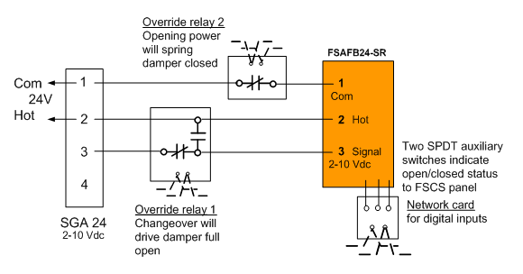
Figure 12: Proportional control of a smoke damper by a minimum potentiometer.
Reversible Fan Ventilation and Smoke Removal
Where there is sufficient relief by local exhausts or return airs in adjacent areas, a reversible fan and only one duct run to all floors is possible. In some cases, a make-up air damper can provide for needed relief. A gravity relief damper is another possibility. This removes the need for a second duct and second damper on each floor. Figure 13 shows the concept.
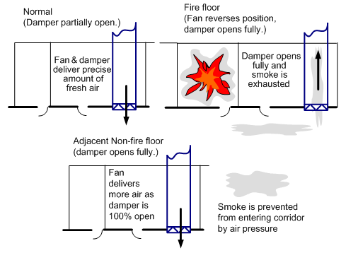
Figure 13 Reversible fan for ventilation or smoke extraction as needed
Summary
A sandwich or building pressurization system approach can be used for corridor smoke control to facilitate egress during a fire or other event. The same duct(s) and damper(s) can be used for ventilation during normal occupancy periods.
There are a number of duct and damper choices available for corridor ventilation and smoke extraction. The Belimo FSAF24-BAL or the FSAFB24-SR with an SGA potentiometer can provide the different sequences of operation needed.
###
References
International Building Code, 2012, International Code Council, Inc. (ICC), Country Club Hills, IL 60478-5795
International Fire Code 2012, ICC, ibid.
International Mechanical Code 2012, ICC, op. cit
UL 555 Standard for Safety for Fire Dampers, Edition 7, 2006, Updated 2010, Underwriters Laboratories Inc. (UL), 333 Pfingsten Road, Northbrook, IL 60062-2096
UL 555S Standard for Safety for Smoke Dampers, 4th Edition, 1999, Updated 2012, ibid.
Written by: Larry Felker, Mechanical Engineer and member of ICC (International Code Council), NFPA (National Fire Protection Association), and a life member of ASHRAE (American Society of Heating, Refrigeration Air Conditioning Engineers). He is a Product Manager for Fire & Smoke Actuators for Belimo Americas who has specialized in fire and smoke dampers and actuators since 2002. Previously he was a temperature control system designer and before that a mechanical and electrical contractor. He is the co-author (with Travis Felker) of Dampers and Airflow Control, ASHRAE Special Publications, 2010, and authored a white paper on Actuated Dampers in Smoke Control Systems.